


1652C/1653B/1654B
Users Manual
30
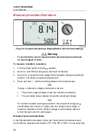
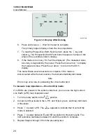
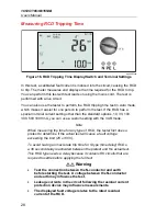
6. Press and release
. Wait for the test to complete.
•
The primary (upper) display shows the trip time.
•
The secondary (lower) display shows the fault voltage (N to PE)
related to the rated residual current.
•
If the trip time is according to the appropriate standard of the RCD, the
RCD
indicator displays. For more information, see Maximum Trip
Time Table on page 54.
To measure RCD tripping time for a custom RCD setting – VAR mode:
1. Turn the rotary switch to the
Δ
T position.
2. Press
to select the VAR current rating. The current custom setting
shows on the primary display. Use the
arrow keys to adjust the value.
3. Press
to select a test current multiplier. Normally you will use x 1/2 or
x 1 for this test.
4. Repeat steps 4 through 6 listed in the preceding RCD tripping time
procedure.
5. To view the nominal setting used for the test, depress the
arrow key.
Note
The maximum setting for type A RCDs is 700 mA. VAR mode is not
available for type B RCDs.
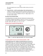
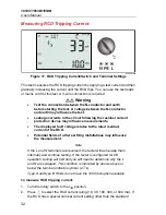
To measure RCD tripping time using Auto mode:
1. Plug the tester into the outlet.
2. Turn the rotary switch to the
Δ
T position.
3. Press
to select the RCD current rating (10, 30, or 100 mA).
4. Press
to select Auto mode.
5. Press
to select the RCD test-current waveform.
6. Press and release
.
The tester supplies ½x the rated RCD current for 310 or 510 ms (2
seconds in the UK). If the RCD trips, the test terminates. If the RCD does
not trip, the tester reverses phase and repeats the test. The test terminates
if the RCD Trips.
If the RCD does not trip, the tester restores the initial phase setting and
supplies 1x the rated RCD current. The RCD should trip and the test
results appear in the primary display.


