Instruction Booklet
IB131006EN
Effective March 2019Supersedes July 2017
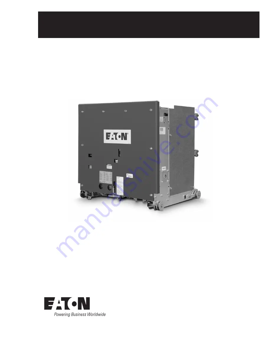
Instructions for installation,
operation, and maintenance of type
VCP-W vacuum circuit breakers
Page 1: ...Instruction Booklet IB131006EN Effective March 2019 Supersedes July 2017 Instructions for installation operation and maintenance of type VCP W vacuum circuit breakers...
Page 2: ...HIN THEIR NAMEPLATE RATINGS OPERATION OUTSIDE OF THESE RATINGS MAY CAUSE THE EQUIPMENT TO FAIL RESULTING IN DEATH SERIOUS PERSONAL INJURY AND PROPERTY DAMAGE ALL SAFETY CODES SAFETY STANDARDS AND OR R...
Page 3: ...pter integrity 28 4 4 Insulation 28 4 5 Contact erosion and wipe 28 4 6 Primary circuit resistance 28 4 7 Nameplate 28 4 8 Electrical operation check 28 4 8 1 Circuit breaker insertion and removal 28...
Page 4: ...aker outlines dim in inches mm 11 Figure 2 Type VCPW ND circuit breaker outlines and dimensions in inches mm 12 Figure 3 Typical VCP W tools and accessories 23 Figure 4 Typical front view VCP W vacuum...
Page 5: ...trical current basis 8 Table 3 ANSI Standards type VCP WC extra capability vacuum circuit breaker 5 27 kV rated symmetrical current basis 9 Table 4 IEC 56 Standardsa type VCP W vacuum circuit breaker...
Page 6: ...LDFACE AS SHOWN BELOW m CAUTION COMPLETELY READ AND UNDERSTAND THE MATERIAL PRESENTED IN THIS DOCUMENT BEFORE ATTEMPTING INSTALLATION OPERATION OR APPLICATION OF THE EQUIPMENT IN ADDITION ONLY QUALIFI...
Page 7: ...MVA kV rms kV rms Amperes kA rms Cycles Seconds kV rms kA rms kA peak kA rms 50VCPW ND250 4 16 250 4 76 1 24 19 60 1200 29 5 2 3 85 36 97 58 50VCP W250 4 16 250 4 76 1 24 19 60 1200 2000 3000 29 5 2 3...
Page 8: ...tor switching cable charging Power frequency 1 min Impulse kV MVA kV rms kV rms Amperes kA rms Cycles Seconds kV rms kA rms kA peak kA rms 270VCP W750 16 e 27 750 27 1 0 60 125 600 1200 2000 16 5 2 51...
Page 9: ...1600i 7 7 7 7 7 7 465 465 465 10 000 10 000 10 000 270 VCP W 25C 27 1 60 125 1200 1600 25 75 36 85 25 h 3 2 1 1 400 20 4 2 2 500 270 VCP W 32C 27 1 60 125 1200 1600 31 5 57 40 97 32 g 3 1 1 1 400 20...
Page 10: ...15 0 164 98 a All circuit breakers are tested to 60 Hz however they can also be applied at 50 Hz with no derating b Consult the Consulting Application Guide CA08104001E sections 1 and 5 for further i...
Page 11: ...VCPW SE and VCP WC circuit breaker outlines and dimensions in inches mm Breaker Identification A B C D E 240 VCP W 270 VCP W 270 VCP WC 10 254 00 14 355 60 16 25 412 75 34 80 883 92 35 22 894 59 50 3...
Page 12: ...enance of type VCP W vacuum circuit breakers EATON www eaton com Figure 2 Type VCPW ND circuit breaker outlines and dimensions in inches mm 21 38 543 05 7 00 177 80 7 00 177 80 3 69 93 73 20 88 530 35...
Page 13: ...aker element is not to be used immediately but is to be placed in storage maximum protection can be obtained by keeping it packed as shipped Upon receipt of the equipment inspect the containers for an...
Page 14: ...to be performed manually approximately 6 turns Non BPI pan assembly Used to electrically move the breaker between DISCONNECT TEST and CONNECTED positions Truck operated cell TOC switch Indicates when...
Page 15: ...and left one set 7813C41G03 Set of rail clamps 6511C83G11 Lifting yoke 691C607G11 Manual charging handle 8064A02G11 Standard set of accessories Spin free levering in crank with clutch Extension rails...
Page 16: ...Manual charging handle 8064A02G11 Set of ND accessories Spin free levering in crank with clutch Primary contact spanner wrench Extension rails right and left one set Manual charging handle Set of rai...
Page 17: ...7G11 Manual charging handle 8064A02G11 Standard set of 27 kV accessories Levering in crank with clutch manual charging handle 1A30136G02 Wheel kit for direct roll in 68C5010G42 Portable lifter 1C19086...
Page 18: ...terminals only 3000 A 66A5092G46 66A5092G06 66A5092G16 Lower terminals only 3000 A 66A5092G47 66A5092G07 66A5092G17 Upper and lower terminals 1200 2000 A with ROF wheels installed 66A5092G82 66A5092G6...
Page 19: ...302G26 3000 A 250 Vdc or 240 Vac 66A5302G27 1200 2000 3000 A 48 Vdc 66A5302G32 1200 2000 3000 A 125 Vdc or 120 Vac 66A5302G33 1200 2000 3000 A 250 Vdc or 240 Vac 66A5302G34 With roll on floor wheels R...
Page 20: ...vice for VCP WXC Description Style number Electrically operated ground and test device Upper terminal 1200 2000 3000 A 125 Vdc or 120 Vac 63 kA 66A5302G83 Lower terminal 1200 2000 3000 A 125 Vdc or 12...
Page 21: ...20 Table 18 VCP W ANSI rated breaker weightsa Rating Amperes Lbs kg 50VCPW ND250 1200 345 157 50VCP W250 50VCPW SE250 1200 2000 3000 350 159 410 186 525 238 50VCP W350 50VCPW SE350 1200 2000 3000 460...
Page 22: ...2000 375 170 410 186 175VCP W25 630 1250 2000 350 159 350 159 410 186 175VCP W32 1250 2000 375 170 410 186 175VCP W40 1250 2000 375 170 410 186 240 VCP W1 6 630 1250 2000 462 210 484 220 506 230 240...
Page 23: ...installation operation and maintenance of type VCP W vacuum circuit breakers EATON www eaton com Figure 3 Typical VCP W tools and accessories Note products shown for representation only New products...
Page 24: ...cuum circuit breakers EATON www eaton com Figure 4 Typical front view VCP W vacuum circuit breaker See Figure 45 for an example of a roll on the floor wheel kit 1 Front panel 2 Lift pull handle 3 Whee...
Page 25: ...front cover removed 1 L H closing spring 2 Anti pump relay 3 Auxiliary switch 4 Motor cutoff switch 5 Closing cam 6 Spring release close coil assembly 7 Shunt trip assembly 8 Charging motor 9 Chargin...
Page 26: ...ce of type VCP W vacuum circuit breakers EATON www eaton com Figure 6 Typical rear view VCP W vacuum circuit breaker element 1 Vacuum interrupter 2 Phase barrier 3 V flex current transfer system 4 Dir...
Page 27: ...type VCP W vacuum circuit breakers EATON www eaton com Figure 7 Typical VCP W vacuum circuit breaker front cover arrangement 1 Front panel 2 Nameplate 3 Operation counter 4 Open closed indicator 5 Ma...
Page 28: ...secondary insulation as described in Section 6 4 5 Contact erosion and wipe Manually charge the closing springs and close the circuit breaker Check contact erosion and wipe as described in Section 6 4...
Page 29: ...res 9 and 10 Figure 9 Insertion of the drawout extension rails Figure 10 Lifting and setting the breaker in the housing Checking pan operation A TEST or DISCONNECT TEST position To operate the breaker...
Page 30: ...hex drive nut on the levering system In order to engage the hex drive nut you must push in the levering system slider 3 Rotate the levering in crank in a counterclockwise direction until the breaker...
Page 31: ...31006EN Effective March 2019 Instructions for installation operation and maintenance of type VCP W vacuum circuit breakers EATON www eaton com Note N The legend for Figures 12 and 13 follow Figure 13...
Page 32: ...n BPI pan assembly 1 2 4 5 7 6 9 8 3 Legends for Figures 12 13 1 Ground contacts 2 Levering system 3 Automatic BPI or manual non BPI secondary 4 Racking screw 5 Moving block 6 Slider 7 Breaker positio...
Page 33: ...pping of a closed breaker by pushing in on the slider item 6 that prevents access to the racking screw Non BPI pan assembly Figure 13 displays the Z shaped slider interlock that prevents a closed brea...
Page 34: ...mpartment There is also a coding plate fastened to the front of the breaker If the breaker has a lower interrupting rating than the rating of the compartment or if the voltage and continuous current c...
Page 35: ...ional Figure 46 It will function the same as the Non BPI pan assembly above due to the replacement of the L bracket with the Z bracket Negative interlock The negative interlock prevents the circuit br...
Page 36: ...position Engage the extension rails Once again disengage the levering latch and pull the circuit breaker out The circuit breaker will trip close and trip as it comes out on to the extension rails fro...
Page 37: ...that the interrupter must be replaced observe the erosion mark placed on each moving stem from the rear of the breaker with the breaker closed The interrupter is satisfactory if the mark on the stem i...
Page 38: ...000 3000 3 4 7 2 INNER 4 2 INNER VCP W K 1 circuit breaker barrier configurations ANSI breaker identification Amps Reference vacuum interrupter diameter inches Number of barriers 150 VCP W40 1200 2000...
Page 39: ...e shaft 2 Main link 3 Banana link 4 Trip latch 5 Shunt trip lever 6 Shunt trip coil 7 Cam shaft 8 Closing cam 9 Operating rod 10 Main link roller 11 Trip bar D shaft 12 Trip latch reset spring Figure...
Page 40: ...ging schematic 1 Pole shaft 2 Anti close interlock 3 Spring release close latch 4 Spring crank 5 Closing spring 6 Closing spring fixed end 7 Spring release close coil 8 Cam shaft 9 Motor ratchet lever...
Page 41: ...close the circuit breaker In Figure 20c the linkage is shown with the circuit beaker in the closed position before the closing springs have been recharged Interference of the trip D shaft with the tr...
Page 42: ...lation operation and maintenance of type VCP W vacuum circuit breakers EATON www eaton com Figure 22 Typical VCP W DC and AC control schemes Dashed lines represent customer wiring and components This...
Page 43: ...ers EATON www eaton com Figure 23 15 kV VCP WXC 63 kA 1200 3000 A special power plant breakers styles 4A35390G10 4A35391G10 4A35392G10 DC control scheme and diagram Dashed lines represent customer wir...
Page 44: ...LES 4A35390G10 4A35391G10 4A35392G10 CIRCUIT BREAKERS ARE CONFIGURED FOR POWER PLANT SPECIFIC APPLICATIONS ONLY POTENTIALLY SEVERE UNINTENDED CONSEQUENCES COULD RESULT IF THESE DEVICES ARE MISAPPLIED...
Page 45: ...enal source it will trip the breaker open The shunt trip device is available with rated voltages of 24 Vdc 48 Vdc 125 Vdc 250 Vdc 120 Vac and 240 Vac A cap trip device must be used with the 120 Vac an...
Page 46: ...operation and maintenance of type VCP W vacuum circuit breakers EATON www eaton com Figure 24 15 kV under voltage trip device configuration 1 Moving clapper 2 Stationary yoke 3 UV trip device coil 4 E...
Page 47: ...the device is a racking screw racking nut and moving block Although the device is mounted in the switchgear compartment a brief description here will help understand the operation Figures 13 and 15 Fo...
Page 48: ...d be immediately inspected and the schedule for inspection and maintenance should be re evaluated based upon the inspec tion results Additionally because of the variability of system fault characteris...
Page 49: ...e is intended as a general guideline and should be applied in conjunction with the experience and good judgment of the individual performing the work m CAUTION OVER TORQUING CAN CAUSE PERMANENT DAMAGE...
Page 50: ...upter assembly and perform contact wipe check If the bushing is NOT intact then glue back the bushing to the cup plate and observe the mark again Replace interrupter assembly If integrity check is not...
Page 51: ...CAL CHARGE BEFORE COMING IN CONTACT WITH THE PRIMARY CIRCUIT To avoid any ambiguity in the AChigh potential test due to leakage or displacement capacitive current the test unit should have sufficient...
Page 52: ...upter showing contact erosion indica tor with breaker closed indicators are checked only when the breaker is closed Figure 29 Wipe indication procedure performed only with the breaker closed Cup plate...
Page 53: ...r each pole The resistance should not exceed the values shown in Table 25 Table 25 Typical resistance measurements Rated continuous current amperes Resistance microohms 1200 2000 3000 60 40 20 6 9 Mec...
Page 54: ...sing spring status indicates Discharged and the main contact indicator shows Open Figure 7 2 Remove the circuit breaker front cover Be sure to save the original fasteners for reassembly 3 Cut a piece...
Page 55: ...g springs 7 Charge the closing springs with the maintenance tool Continue charging the closing springs until a click is heard and the status indicator shows Charged Figure 35 8 While holding the marke...
Page 56: ...ove the marker from hole C 11 Push the push to open clapper to open the circuit breaker Figure 43 Front view of closure tool showing mounting testing locations 6352C49H01 12 Inspect the circuit breake...
Page 57: ...e grease with no side effects For breakers built after 1 1 2018 All parts that require lubrication have been lubricated during the assembly with Eaton s new synthetic grease Over a period of time this...
Page 58: ...latch binding Close latch roller binding Trip circuit energized Undesirably closes Control circuit Close circuit CS C getting shorted Mechanism Close release latch fails to reset Close floor tripper...
Page 59: ...50 250 2000 A 58 kA 50 250 2000 A 58 kA 5 SC 50 250H 2000 A 78 kA 8297A02H01 8297A02H21 8297A05H01 8297A03H01 8297A03H21 8297A06H01 8297A02H02 8297A02H22 8297A05H02 8297A03H02 8297A03H22 8297A06H02 82...
Page 60: ...1 000 1200 A 77 kA 5 LT 150 1000C 1200 A 77 kA 5 LT 150 1 000 2000 A 77 kA 7 150 1 000 2000 A 77 kA 5 150 1 000 2000 A 77 kA 5 LT 150 1000C 2000 A 77 kA 5 LT 150VCP W40C 1200 A 1 50VCP W40C 2000 A 150...
Page 61: ...to 15kV Interphase barriers 2000 A outside Barriers 1200 2000 A 694C549G03 694C549G06 694C549G03 694C549G06 4 Barriers 694C622G03 694C622G03 1 1 36 Up to 15 kV All 50 350 150 1000 150 63 and 3000 A br...
Page 62: ...3 1 1 1 50 Rectifier 1 20 240 Vac 3759A79G02 3759A79G01 1 1 51 52 53 54 55 Anti pump Y relay 48 Vdc 125 Vdc 250 Vdc 120 Vac 240 Vac 3759A74G03 3759A74G04 3759A74G05 3759A74G01 3759A74G02 8237A27H03 82...
Page 63: ...01 3759A93G01 699B147H01 3759A93H02 8064A03G01 3759A93G01 1 1 66 Auxiliary switch 698B822H01 5697B02G01 5697B02G02 1 67 Trip D shaft 694C638G02 694C638G02 694C638G02 1 68 Main link trip latch 3A75675G...
Page 64: ...Typical view VCP WC 101 102 103 Interrupter Assembly 50 25C 1200 A 50 25C 2000 A 50 25C 3000 A 8297A33H01 8297A33H02 8297A33H03 3 3 3 104 105 106 50 40C 1200 A 50 40C 2000 A 50 40C 3000 A 8297A34H01...
Page 65: ...8299A01H05 3 3 6 7 36 40 1250 A 36 40 2000 A 8299A01H06 8299A01H07 3 3 8 9 10 72 25 630 A 72 25 1250 A 72 25 2000 A 8299A01H08 8299A01H09 8299A01H10 3 3 3 11 12 72 32 1250 A 72 32 2000 A 8299A01H11 8...
Page 66: ...Up to 17 5 kV 24 kV 28 29 29A 240 25 650 A 240 25 1250 A 240 25 2000 A 8299A01H28 8299A01H29 8299A01H30 3 3 3 30 31 Primary disconnects Up to 175 40 630 A Up to 175 40 1250 A 699B104G01 699B104G01 6...
Page 67: ...G03 699B196G01 699B196G02 699B196G06 699B196G04 699B196G05 1 1 1 46 Motor brush kit 8063A77G01 8063A77G01 1 47 48 49 Spring release coils 48 Vdc 125 Vdc 120 Vac 250 Vdc 240 Vac 3759A76G01 3759A76G02 3...
Page 68: ...V trip coils 48 Vdc 125 Vdc 250 Vdc 120 AC 240 AC 8064A19G01 8064A19G02 8064A19G03 8064A19G09 8064A19G08 8064A19G01 8064A19G02 8064A19G03 8064A19G07 8064A19G08 1 1 1 1 1 63 Motor cut off switch 699B19...
Page 69: ...heel 3617A99G01 3617A99G01 74 Fastener kit 8061A01G01 8061A01G01 75 Labels kit 3759A79G01 8295A45G04 1 76 Wiring harness repair kit complete replacement 691C281G01 691C281G03 691C281G04 691C281G01 691...
Page 70: ...center wheel on the 27 kV roll on the floor breaker is rotated 180 degrees from the picture shown above to align better with the center of gravity 8 2 Optional automatic manual hybrid secondary for BP...
Page 71: ...been developed for the BPI pan assembly to reduce the required force to manually rack in a 63 kA or 3 000 A breaker If the customer is using a MR2 system to lever in the breakers then this system is n...
Page 72: ...contractual agreement between Eaton and the purchaser THERE ARE NO UNDERSTANDINGS AGREEMENTS WARRANTIES EXPRESSED OR IMPLIED INCLUDING WARRANTIES OF FITNESS FOR A PARTICULAR PURPOSE OR MERCHANTABILIT...