USER INSTRUCTIONS POLYCHEM GRP ENGLISH 71569132 12-04A
Page 37 of 52
flowserve.com
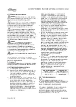
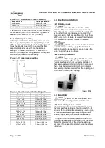
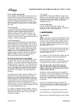
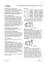
This unit will appear as shown in figure 6-14.
Further disassembly is not required unless the
bearings are to be replaced.
Figure 6-13
Figure 6-14
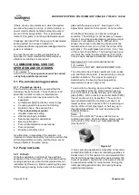
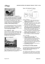
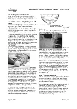
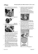
d) Remove the snap ring [2530.1] (figure 6-15) on
Group 1 and 2 pumps, or the bearing retainer
[2530.2] on Group 3 pumps.
Figure 6-15
Group 1 and 2 pumps equipped with
duplex angular contact bearings use a bearing
retainer [2530.2] instead of the snap ring.
Remove the carrier from the bearing.
e) The bearing locknut [3712.1] and lockwasher
[6541.1] may now be removed from the shaft
[2100]. Discard the lockwasher.
f) An arbor or hydraulic press may be used to
remove the bearings [3011 and 3013] from the
shaft. It is extremely important to apply even
pressure to the inner bearing race only. Never
apply pressure to the outer race as this exerts
excess load on the balls and causes damage.
Applying pressure to the outer
race could permanently damage the bearings.
g) The Mark 3A design has an optional oil slinger
[2541] located between the bearings. If present,
inspect it for damage or looseness. Remove if it
needs to be replaced.
h) On Group 2 and 3 pumps, the bearing housing
[3200] must be separated from the bearing
housing adapter [1340]. The adapter O-ring
[4610.3] should be discarded.
Mark 3A and ANSI 3A design.
This is
accomplished by removing the cap screws
[6570.6], which thread into the bearing housing.
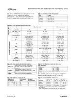
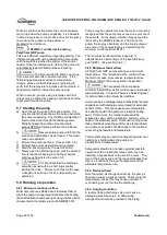
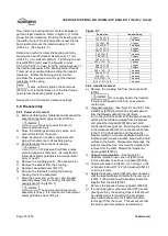
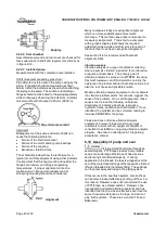
i) If lip seals [4310.1 and 4310.2] (figure 6-16) are
used, they should be removed from the bearing
carrier and adapter and discarded.
Figure 6-16
j) If the bearing isolators are removed from either
the bearing carrier or adapter they must not be
reused, discard appropriately.
k) If magnetic seals are used, maintain the seals as
specified by the manufacturer.
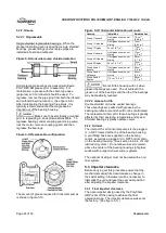
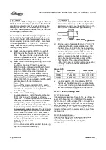
l)
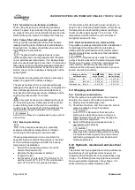
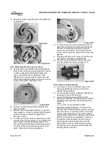
Remove site gage, oil level tag and oiler (if used).
Mark 3A design
. Remove the Trico oiler/site
gage [3855] (figure 6-17) and oil level tag (figure
6-18) from the bearing housing.
ANSI 3A design
. Remove the site gage [3856]
(figure 5-1) and oil level tag (figure 6-18) from the
bearing housing. Save these parts for reuse.
Figure 6-17
Figure 6-18

