background image


USER INSTRUCTIONS POLYCHEM GRP  ENGLISH  71569132  12-04A 

Page 2 of 52 

flowserve.com


CONTENTS 

Page 

1  INTRODUCTION AND SAFETY ........................... 4


1.1  General ......................................................... 4


1.2  CE marking and approvals ............................. 4


1.3  Disclaimer...................................................... 4


1.4  Copyright ....................................................... 4


1.5  Duty conditions .............................................. 4


1.6  Safety ............................................................ 5


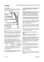
1.7  Nameplate and safety labels .......................... 8


1.8  Specific machine performance ....................... 9


1.9  Noise level ..................................................... 9


2  TRANSPORT AND STORAGE ........................... 10


2.1  Consignment receipt and unpacking ............ 10


2.2  Handling ...................................................... 10


2.3  Lifting .......................................................... 10


2.4  Storage........................................................ 10


2.5  Recycling and end of product life ................. 11


3  DESCRIPTION .................................................. 11


3.1  Configurations ............................................. 11


3.2  Name nomenclature .................................... 11


3.3  Design of major parts ................................... 12


3.4  Performance and operating limits ................. 12


4  INSTALLATION .................................................. 13


4.1  Location....................................................... 13


4.2  Part assemblies ........................................... 13


4.3  Foundation .................................................. 13


4.4  Grouting ...................................................... 15


4.5  Initial alignment............................................ 16


4.6  Piping .......................................................... 17


4.7  Electrical connections .................................. 23


4.8  Final shaft alignment check .......................... 23


4.9  Protection systems ...................................... 23


5  COMMISSIONING, START-UP, OPERATION  

AND SHUTDOWN .......................................... 24


5.1  Pre-commissioning procedure ...................... 24


5.2  Pump lubricants ........................................... 24


5.3  Impeller clearance ....................................... 26


5.4  Direction of rotation ...................................... 27


5.5  Guarding ..................................................... 27


5.6  Priming and auxiliary supplies ...................... 28


5.7  Starting the pump ........................................ 29


5.8  Running or operation ................................... 29


5.9  Stopping and shutdown ............................... 30


5.10  Hydraulic, mechanical and electrical duty ... 30


Page 

6  MAINTENANCE ................................................ 31


6.1  General ....................................................... 31


6.2  Maintenance schedule ................................ 32


6.3  Spare parts ................................................. 32


6.4  Recommended spares and  

consumable items ..................................... 33


6.5  Tools required ............................................. 33


6.6  Fastener torques ......................................... 33


6.7  Setting impeller clearance ........................... 34


6.8  Disassembly ............................................... 35


6.9  Examination of parts ................................... 38


6.10  Assembly of pump and seal ....................... 40


7  FAULTS; CAUSES AND REMEDIES ................. 45


8  PARTS LISTS AND DRAWINGS........................ 48


8.1  PolyChem GRP pump, Group 1................... 48


8.2  PolyChem GRP pump, Group 2................... 49


8.3  PolyChem GRP pump, Group 3................... 50


8.4  General arrangement drawing ..................... 51


9  CERTIFICATION ............................................... 51


10  OTHER RELEVANT DOCUMENTATION  

AND MANUALS ............................................. 51


10.1  Supplementary User Instruction manuals .. 51


10.2  Change notes............................................ 51


10.3  Additional sources of information ............... 51


Summary of Contents for PolyChem GRP 1J1.5x1G-6

Page 1: ...iming non metallic frame mounted pump PCN 71569132 12 04A E Original instructions These instructions must be read prior to installing operating using and maintaining this equipment Компания ПромХимТех официальный дистрибьютор насосов Flowserve www promhimtech ru Тел 8 800 250 01 54 e mail zakaz promhimtech ru ...

Page 2: ...systems 23 5 COMMISSIONING START UP OPERATION AND SHUTDOWN 24 5 1 Pre commissioning procedure 24 5 2 Pump lubricants 24 5 3 Impeller clearance 26 5 4 Direction of rotation 27 5 5 Guarding 27 5 6 Priming and auxiliary supplies 28 5 7 Starting the pump 29 5 8 Running or operation 29 5 9 Stopping and shutdown 30 5 10 Hydraulic mechanical and electrical duty 30 Page 6 MAINTENANCE 31 6 1 General 31 6 2...

Page 3: ...13 Lubrication see 5 2 24 Maintenance 6 31 Maintenance schedule 6 2 32 Name nomenclature 3 2 11 Nameplate 1 7 1 8 Operating limits see 3 4 12 Ordering spare parts 6 3 1 32 Part assemblies 4 2 13 Parts lists see 8 48 Performance 3 4 12 Piping 4 6 17 Pre commissioning 5 1 24 Priming and auxiliary supplies 5 6 28 Protection systems 4 9 23 Page Reassembly see 6 10 Assembly 40 Receipt and unpacking 2 1...

Page 4: ...cable the Directives and any additional Approvals cover important safety aspects relating to machinery and equipment and the satisfactory provision of technical documents and safety instructions Where applicable this document incorporates information relevant to these Directives and Approvals To confirm the Approvals applying and if the product is CE marked check the serial number plate markings a...

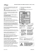
Page 5: ...l appropriate training and instruction must be provided If required the operator may commission the manufacturer supplier to provide applicable training Always coordinate repair activity with operations and health and safety personnel and follow all plant safety requirements and applicable safety and health laws and regulations 1 6 3 Safety action This is a summary of conditions and actions to hel...

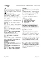
Page 6: ...MP SHAFT MUST TURN CLOCKWISE WHEN VIEWED FROM THE MOTOR END It is absolutely essential that the rotation of the motor be checked before installation of the coupling spacer and starting the pump Incorrect rotation of the pump for even a short period can unscrew the impeller which can cause significant damage 1 6 4 Products used in potentially explosive atmospheres Measures are required to Avoid exc...

Page 7: ...th the specified maximum liquid temperature is with the plant operator Temperature classification Tx is used when the liquid temperature varies and when the pump is required to be used in differently classified potentially explosive atmospheres In this case the user is responsible for ensuring that the pump surface temperature does not exceed that permitted in its actual installed location Do not ...

Page 8: ...f the pump is stationary or running Bursting of liquid containing parts due to freezing must be avoided by draining or protecting the pump and ancillary systems Where there is the potential hazard of a loss of a seal barrier fluid or external flush the fluid must be monitored If leakage of liquid to atmosphere can result in a hazard install a liquid detection device 1 6 4 7 Maintenance to avoid th...

Page 9: ... the pump only noise levels in the table should be combined with the level for the driver obtained from the supplier Consult Flowserve or a noise specialist if assistance is required in combining the values It is recommended that where exposure approaches the prescribed limit then site noise measurements should be made The values are in sound pressure level LpA at 1 m 3 3 ft from the machine for f...

Page 10: ...casing body 2 3 1 2 Rear cover 1220 Use a choker hitch slung through the central seal chamber hole to lift large rear covers 2 3 1 3 Bearing housing 3200 Group 1 Insert a sling between the upper and lower support ribs between the housing barrel and the casing attachment flange Use a choker hitch when slinging Make sure there are no sharp edges on the bottom side of the ribs which could cut the sli...

Page 11: ...utions 2 5 Recycling and end of product life At the end of the service life of the product or its parts the relevant materials and parts should be recycled or disposed of using an environmentally acceptable method and local requirements If the product contains substances that are harmful to the environment these should be removed and disposed of in accordance with current regulations This also inc...

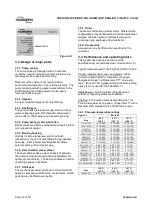
Page 12: ... internal combustion engines turbines hydraulic motors etc driving via couplings belts gearboxes drive shafts etc 3 3 9 Accessories Accessories may be fitted when specified by the customer 3 4 Performance and operating limits This product has been selected to meet the specification of your purchase order See section 1 5 Typical materials used in the PolyChem GRP include Casing impeller rear cover ...

Page 13: ...m submergence 3 4 4 Suction pressure limits Open style impellers typically create a thrust load towards the suction of the pump This reduces the axial loading on the bearings so that the suction pressure limit is equal to the pressure temperature rating 4 INSTALLATION Equipment operated in hazardous locations must comply with the relevant explosion protection regulations See section 1 6 4 Products...

Page 14: ...y moving the motor to match the pump Flowserve practice is to confirm in our shop that the pump assembly can be accurately aligned Before shipment the factory verifies that there is enough horizontal movement capability at the motor to obtain a perfect final alignment when the installer puts the baseplate assembly into its original top leveled unstressed condition 4 3 3 Stilt and spring mounted ba...

Page 15: ... baseplates is similar to grouted baseplates The difference is primarily in the way the baseplate is leveled a Level the baseplate by using the stilt adjusters Shims are not needed as with grouted baseplates After the base is level it is locked in place by locking the stilt adjusters b Next the initial pump alignment must be checked The vertical height adjustment provided by the stilts allows the ...

Page 16: ... done in a way that ensures that if the installer duplicates the factory conditions there will be sufficient clearance between the motor hold down bolts and motor foot holes to move the motor into final alignment If the pump and motor were properly reinstalled to the baseplate or if they were not removed from the baseplate and there has been no transit damage and also if the above steps where done...

Page 17: ...emoved from the pump before connecting any pipes 4 6 1 Suction and discharge pipework Never use pump as a support for piping All piping must be independently supported accurately aligned and preferably connected to the pump by a short length of flexible piping The pump should not have to support the weight of the pipe or compensate for misalignment It should be possible to install suction and disc...

Page 18: ...et or exceed the allowable nozzle loads given by ANSI HI 9 6 2 The following paragraphs describe how to calculate the allowable loads for each pump type and how to determine if the applied loads are acceptable The following steps are based upon ANSI HI 9 6 2 All information necessary to complete the evaluation is given below For complete details please review the standard a Find the Baseplate Corr...

Page 19: ... M F F F F F F Adjusted 4 12 Maximum individual loading 2 0 2 _ _ _ _ _ _ _ _ _ _ _ _ adj zd zd adj yd yd adj xd xd adj zd zd adj yd yd adj xd xd adj zs zs adj ys ys adj xs xs adj zs zs adj ys ys adj xs xs M M M M M M F F F F F F M M M M M M F F F F F F Adjusted 4 13 Nozzle stress bolt stress pump slippage 3 adj zd zd adj yd yd adj xd xd adj yd yd adj zs zs adj ys ys adj xs xs adj ys ys M M M M M ...

Page 20: ...0 3 558 800 6 005 1350 13 344 3 000 556 410 556 410 556 410 1J 3x1 5G 6 4 670 1 050 5 516 1 240 5 560 1 250 1 220 900 664 490 664 490 3 558 800 6 005 1 350 13 344 3 000 678 500 746 550 692 510 1J 3x2G 6 4 670 1 050 4 670 1 050 4 670 1 050 1 220 900 298 220 298 220 3 558 800 6 005 1 350 13 344 3 000 678 500 1 356 1 000 692 510 1K 3x2GS 7 4 670 1 050 4 670 1 050 4 670 1 050 1 220 900 298 220 298 220...

Page 21: ...240 1 980 1 460 1 980 1 460 936 690 2K 6x4G 10 12 010 2 700 6 005 1 350 27 756 6 240 5 058 3 730 1 492 1 100 1 492 1 100 8 985 2 020 6 005 1 350 27 756 6 240 4 204 3 100 4 204 3 100 936 690 2K 3x1 5G 13 12 010 2 700 6 005 1 350 13 611 3 060 5 058 3 730 909 670 909 670 8 985 2 020 6 005 1 350 27 756 6 240 719 530 719 530 719 530 2K 4x3G 13 12 010 2 700 6 005 1 350 10 631 2 390 5 058 3 730 542 400 5...

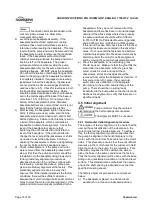
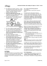
Page 22: ... the stuffing box prior to shipment The packing is shipped with the pump It is the pump installer s responsibility to install the packing in the stuffing box Failure to ensure that packing is installed may result in serious leakage of the pumped fluid 4 6 6 3 Piping connection seal packing support system If the pump has a seal support system it is mandatory that this system be fully installed and ...

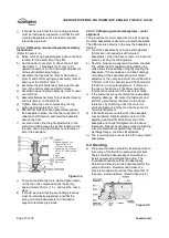
Page 23: ... 0025 mm mm 0 0025 in in FIM angular Stilt mounted baseplates If initial alignment cannot be achieved with the motor fasteners centered the baseplate may be twisted Slightly adjust one turn of the adjusting nut the stilts at the driver end of the baseplate and check for alignment to the above tolerances Repeat as necessary while maintaining a level condition as measured from the pump discharge fla...

Page 24: ...enter of the oil sight glass with the proper type oil See figure 5 2 for approximate amount of oil required do not overfill On the Mark 3A design an optional oil slinger is available The oil slinger is not necessary however if used it provides an advantage by allowing a larger tolerance in acceptable oil level Without an oil slinger the oil level in the bearing housing must be maintained at 3 mm 1...

Page 25: ...ydn 32 Q8 Verdi 68 Q8 Haydn 68 Q8 Verdi 46 Q8 Haydn 46 Shell Shell Tellus 32 Shell Tellus 37 Shell Tellus 01 C 68 Shell Tellus 01 68 Shell Tellus 01 C 46 Shell Tellus 01 46 Texaco Rando Oil HD 32 Rando Oil HD AZ 32 Rando Oil 68 Rando Oil HD C 68 Rando Oil 46 Rando Oil HD B 46 Wintershall BASF Group Wiolan HN32 Wiolan HS32 Wiolan HN68 Wiolan HS68 Wiolan HN46 Wiolan HS46 Figure 5 4 General lubricant...

Page 26: ...lex 68 cm 3 4 1 in 3 34 cm 3 2 1 in 3 Group 3 and 4 Inboard Until grease comes out of plug 30 cm 3 1 8 in 3 Group 3 and 4 Outboard Until grease comes out of plug 54 cm 3 3 3 in 3 Group 3 and 4 Duplex 115 cm 3 7 0 in 3 60 cm 3 3 7 in 3 Do not fill the housing with oil when greased bearings are used The oil will leach the grease out of the bearings and the life of the bearings may be drastically red...

Page 27: ...3J12 x 10 x 15 17 45 mm 0 687 in 4J12 x 10 x 15B 17 45 mm 0 687 in 5 4 Direction of rotation 5 4 1 Rotation check It is absolutely essential that the rotation of the motor is checked before connecting the shaft coupling Incorrect rotation of the pump for even a short time can dislodge and damage the impeller casing shaft and shaft seal All PolyChem GRP pumps turn clockwise as viewed from the motor...

Page 28: ...ing a Measure minimum distance from the center of mounting hole in the baseplate to the motor at diameter as shown above b Locate a reference center of the slot in the coupling guard flange Transfer measurement from step 1 to the guard using this reference center c Trim the motor end of guard according to the above measurement Trimming is best done with a band saw but most other types of manual or...

Page 29: ...ate and still meet the bearing life shaft deflection and bearing housing vibration limits documented in the latest version of ASME B73 1M Pumps may be operated at lower flows but it must be recognized that the pump may exceed one or more of these limits For example vibration may exceed the limit set by the ASME standard The size of the pump the energy absorbed and the liquid pumped are some of the...

Page 30: ...y maximum ambient temperature tb Set the alarm at t tb ta 5 ºC t tb ta 10 ºF and the trip at 100 ºC 212 ºF for oil lubrication and 105 ºC 220 ºF for grease lubrication It is important particularly with grease lubrication to keep a check on bearing temperatures After start up the temperature rise should be gradual reaching a maximum after approximately 1 5 to 2 hours This temperature rise should th...

Page 31: ...n of the pump and particularly accelerations as the fluid enters the impeller vanes The value for NPSHR for the specific pump purchased is given in the pump data sheet and on the pump performance curve For a pump to operate properly the NPSHA must be greater than the NPSHR Good practice dictates that this margin should be at least 1 5 m 5 ft or 20 whichever is greater Ensuring that NPSHA is larger...

Page 32: ...ecommendations in this manual c Contact Flowserve if the problem persists 6 2 1 Preventive maintenance The following sections of this manual give instructions on how to perform a complete maintenance overhaul However it is also important to periodically repeat the Pre start up checks listed in section 5 1 These checks will help extend pump life as well as the length of time between major overhauls...

Page 33: ...rivers Soft mallet More specialized equipment Bearing pullers Bearing induction heater Dial test indicator Flowserve Mark 3 tool kit See 6 1 below Figure 6 1 Flowserve Mark 3 tool kit 6 6 Fastener torques Figure 6 2 Recommended bolt torques ISO US Item Description Group 1 Non lubricated Group 2 Non lubricated Group 3 Non lubricated n a Suction and discharge flange bolting 41 Nm 30 lbf ft 41 Nm 30 ...

Page 34: ...eller axially 0 1 mm 0 004 in See figure 6 5 Tightening the set screws 6570 3 will cause the impeller to move 0 05 mm 0 002 in closer to the rear cover because of the internal looseness in the bearing carrier threads This must be considered when setting the impeller clearance Figure 6 5 Lastly uniformly tighten the set screws 6570 3 in incremental steps up to the final torque value to lock the bea...

Page 35: ... assembly is heavy It is important to follow plant safety guidelines when lifting it Figure 6 7 Pump size Impeller fixing 1J1 5 x 1G 6 Polygon 1J3 x 1 5G 6 Threaded 1J3 x 2G 6K Polygon 1K3 x 2GS 7 Threaded 1J1 5 x 1G 8 Polygon 2K3 x 1 5G 8 Polygon 2K3 x 2G 8 Threaded 2K4 x 3G 8 Polygon 2K2 x 1G 10 Threaded 2K3 x 1 5G 10 Polygon 2K4 x 3G 10 Polygon 2K6 x 4G 10 Polygon 2K3 x 1 5G 13 Threaded 2K4 x 3...

Page 36: ... is used remove the gland and the stationary seat Remove the stationary seat from the gland Loosen the set screws in the rotating unit and remove it from the shaft Discard all O rings and gaskets f If packing 4130 is used remove it and the seal cage 4134 Remove the gland 4120 g The shaft sleeve 2400 can now be removed Unit now appears as shown in figure 6 12 Figure 6 12 6 8 4 Power end disassembly...

Page 37: ...manently damage the bearings g The Mark 3A design has an optional oil slinger 2541 located between the bearings If present inspect it for damage or looseness Remove if it needs to be replaced h On Group 2 and 3 pumps the bearing housing 3200 must be separated from the bearing housing adapter 1340 The adapter O ring 4610 3 should be discarded Mark 3A and ANSI 3A design This is accomplished by remov...

Page 38: ...or seal vendors mm in Suggested and or provided by Flowserve mm in Shaft Diameter tolerance under bearings N S 0 005 0 0002 Impeller Balance See note 1 Bearing housing Diameter ID tolerance at bearings N S 0 013 0 0005 Power end assembly Shaft runout Shaft sleeve runout Radial deflection static Shaft endplay 0 05 0 002 0 05 0 002 N S N S 0 03 0 001 0 05 0 002 0 076 0 003 0 05 0 002 0 05 0 002 0 05...

Page 39: ...undness of the shaft any eccentricity between the shaft and the sleeve any permanent bend in the shaft and or any eccentricity in the way the shaft or bearings are mounted in the bearing housing Shaft run out can shorten the life of the bearings and the mechanical seal Figure 6 21 Group 1 Group 2 Group 3 OB bearing carrier mm in Bearing 71 999 71 986 2 8346 2 8341 110 000 109 985 4 3307 4 3301 150...

Page 40: ...Vibration analysis Vibration analysis is a type of condition monitoring where a pump s vibration signature is monitored on a regular periodic basis The primary goal of vibration analysis is extension on MTBPM By using this tool Flowserve can often determine not only the existence of a problem before it becomes serious but also the root cause and possible solution Modern vibration analysis equipmen...

Page 41: ...310 2RS1C3 5310 A2RSC3 or 3310 A2RS1C3 NA 7 3 Oil bath mist open 1 6314 C3 5314 AC3 or 3314 AC3 7314 BECBY Regreasable single shielded 2 6314 ZC3 5314 AZC3 or 3314 AZC3 NA 6 Greased for life double shielded 3 6314 2ZC3 5314 A2ZC3 or 3314 A2ZC3 NA 7 Sealed for life double sealed 4 6314 2RS1C3 5314 A2RSC3 or 3314 A2RS1C3 NA 7 Notes 1 These bearings are open on both sides They are lubricated by oil b...

Page 42: ...ainst the shaft shoulder Duplex angular contact bearings Duplex angular contact bearings must be mounted back to back with the wider thrust sides of the outer races in contact with each other as shown in figure 6 24 Only bearings designed for universal mounting should be used SKF s designation is BECB NTN s designation is G A special shaft is required when using duplex angular contact bearings It ...

Page 43: ...tall the set screws 6570 3 loosely d Reinstall any tags plugs site gages and oiler Mark 3A design Install the following items onto the bearing housing oil level tag figure 6 18 and combination Trico oiler site gage 3855 vent breather 6521 and drain plug 6569 ANSI 3A design Install the following items onto the bearing housing oil level tag figure 6 18 and site gage 3855 plug 6521 and magnetic drain...

Page 44: ... setup would be as described below f Start machining across the outer diameter Machine from both sides to the middle Continue with additional cuts until the required impeller diameter is achieved g The finished impeller can then be removed from the lathe and installed in the pump No mechanical balancing or resin coating of the vane tips is required 6 10 3 1 Polygon impeller drive units a Position ...

Page 45: ... to one of the books listed in section 10 3 Sources of additional information or contact a Flowserve Sales Engineer or Distributor Representative for assistance Fault symptom Pump not reaching design flow rate Pump not reaching design head TDH No discharge or flow with pump running Pump operates for short period then loses prime Excessive noise from wet end Excessive noise from power end PROBABLE ...

Page 46: ...m to avoid adverse fluid rotation as it approaches the impeller Bearing contamination appearing on the raceways as scoring pitting scratching or rusting caused by adverse environment and entrance of abrasive contaminants from atmosphere 1 Work with clean tools in clean surroundings 2 Remove all outside dirt from housing before exposing bearings 3 Handle with clean dry hands 4 Treat a used bearing ...

Page 47: ...k all parts for proper fit and alignment Bearing damaged by electric arcing identified as electro etching of both inner and outer ring as a pitting or cratering Electrical arcing is caused by a static electrical charge emanating from belt drives electrical leakage or short circuiting 1 Where current shunting through the bearing cannot be corrected a shunt in the form of a slip ring assembly should...

Page 48: ...peller 3855 Oiler optional 3856 Sight gage bearing housing 4120 Gland clamped seat 4200 Mechanical seal 4310 1 Oil seal inboard 4310 2 Oil seal outboard 4590 1 Gasket cover nose 4590 2 Gasket seat to gland 4590 3 Gasket impeller to sleeve 4590 4 Gasket nose cone nut 4610 1 O ring cover 4610 2 O ring bearing carrier 4610 4 O ring sleeve to shaft 6521 Vent plug 6541 1 Lockwasher bearing 6541 2 Lockw...

Page 49: ...al 3856 Sight Gage bearing housing 4120 Gland clamped seat 4200 Mechanical seal 4310 1 Oil seal inboard 4310 2 Oil seal outboard 4590 1 Gasket cover nose 4590 2 Gasket seat to gland 4590 3 Gasket impeller to sleeve 4590 4 Gasket nose cone nut 4610 1 O ring cover 4610 2 O ring bearing carrier 4610 3 O ring adapter to bearing housing 4610 4 O ring sleeve to shaft 6521 Vent plug 6541 1 Lockwasher bea...

Page 50: ...ing 4120 Gland clamped seat 4200 Mechanical seal 4310 1 Oil seal inboard 4310 2 Oil seal outboard 4590 1 Gasket cover nose 4590 2 Gasket seat to gland 4590 3 Gasket impeller to sleeve 4590 4 Gasket nose cone nut 4610 1 O ring cover 4610 2 O ring bearing carrier 4610 3 O ring adapter to bearing housing 4610 4 O ring sleeve to shaft 6521 Vent plug 6541 1 Lockwasher bearing 6541 2 Lockwasher casing 6...

Page 51: ...oiding copying these they are included at the end of these User Instructions such as within a standard clear polymer software protection envelope 10 2 Change notes If any changes agreed with Flowserve Pump Division are made to the product after its supply a record of the details should be maintained with these User Instructions 10 3 Additional sources of information The following are excellent sou...

Page 52: ...port Locator System found at www flowserve com FLOWSERVE REGIONAL SALES OFFICES USA and Canada Flowserve Corporation 5215 North O Connor Blvd Suite 2300 Irving Texas 75039 5421 USA Telephone 1 972 443 6500 Fax 1 972 443 6800 Europe Middle East Africa Flowserve FSG Italy Worthington S r l Via Rossini 90 92 20033 Desio Milan Italy Telephone 39 0362 6121 Fax 39 0362 628 882 Latin America and Caribbea...

Reviews: