background image

Limitorque Master Station III  FCD LMENIM5001-02 – 12/13

28

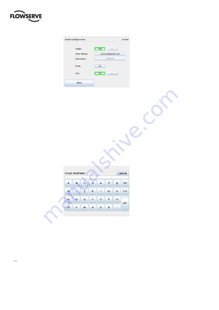
Figure 7.5 - SMTP Configuration with Password 

Once the SMTP Host Address and SMTP Email Account have been configured, the IP address of the 
Master Station III must be set in the Email Notification Screen. Set the Primary and Secondary DNS 
addresses by selecting the octet fields.

7.2.2 Alarm Listener Configuration

Once the SMTP configuration has been completed, alarm listeners can be added to the email notifica-
tion system so that email alerts are sent when any of the following network events occur: Network 
Fault, DCS Port Fault, Emergency Shutdown, Hot Standby Change, or MOV Alerts. Any or all of the 
Master Station III events can be selected for each individual listener.

To add an event listener, click the “Add” button on the Email Notification Screen and enter the desired 
email address as shown in Figure 7.6.

Figure 7.6 - Add Email Listener 

Summary of Contents for LMENIM5001-02

Page 1: ...USER INSTRUCTIONS Installation Operation Maintenance Limitorque Master Station III FCD LMENIM5001 02 12 13 Experience In Motion ...

Page 2: ...ront Panel Connections 16 Figure 4 5 Debug Port Connection 16 Figure 4 6 Modbus Redundant Loop Topology 18 Figure 5 1 The Main Menu Screen 19 Figure 5 2 System Status 20 Figure 5 3 Network Status 20 Figure 5 4 MOV Status 21 Figure 5 5 MSIII Status 21 Figure 6 1 Main Menu 22 Figure 6 2 System Control 23 Figure 6 3 MOV Control 23 Figure 6 4 Control Relays 23 Figure 6 5 Emergency Shutdown 24 Figure 6...

Page 3: ...CS Data Table 40 Figure 8 23 FC 02 Read Input Status 41 Figure 8 24 Modbus Holding Registers 44 Figure 8 25 FC 03 Sample Data Table 45 Figure 8 26 ModBus Coils 49 Figure 8 27 FC 05 15 Sample Data Table 49 Figure 8 28 Modbus Holding Registers One Per MOV 51 Figure 8 29 Modbus Holding Registers Two Per MOV 51 Figure 8 30 FC 06 16 Sample Data Table with One Per MOV Selected 52 Figure 8 31 FC 06 16 Sa...

Page 4: ... B Connection 15 Table 8 1 Status Bit Definitions 41 43 Table 8 2 Function Code 02 Example Message Breakdown 44 Table 8 3 Function Code 03 Example Message Breakdown 45 Table 8 4 Register Definitions 46 48 Table 8 5 DDC 100 Coil Assignments Modbus 05 Command Usage for Digital Outputs 50 Table 8 6 Function Code 05 Example Message Breakdown 50 Table 8 7 Function Code 15 Example Message Breakdown 51 T...

Page 5: ...le Overview The Master Station requires users to login Four user role levels are configurable for each user View Control Configure and Administrator Each role includes the rights of the lesser roles i e Control includes View s rights and Configure includes Control s rights and View s rights VIEW the user can view the network status and the activity log No control or configuration functionality is ...

Page 6: ...any part of the screen will load the Enter User Name screen Figure 1 2 NOTE If the screen is blank and the green LED is illuminated the unit is in screen saver mode Touch the display to exit the screen saver mode Figure 1 2 Enter User Name Once the user name has been entered the Enter Password screen will be displayed Figure 1 3 NOTE Each user name must have a unique password Figure 1 3 Login ...

Page 7: ...parate logical section of the Master Station SYSTEM STATUS ALL USERS View information related to the network status status of the Master Station and MOV status SYSTEM CONTROL CONTROL CONFIGURE AND ADMINISTRATOR Access to MOV control and emergency shutdown functions EMAIL CONFIGURATION CONFIGURE AND ADMINISTRATOR View and change settings related to email alerts SYSTEM CONFIGURATION CONFIGURE AND AD...

Page 8: ...RTU 7 Communication protocol MSIII to Host System Modbus RTU or Modbus TCP IP 8 Network topology Bi directional redundant loop or multi drop daisy chain 9 Physical layer MSIII to field units EIA 485 RS 485 10 Physical layer MSIII to Host System TIA 232 RS 232 EIA 485 RS 485 EIA 422 RS 422 Ethernet 11 Unit redundancy options MSIII module redundancy isolated power connections standard 12 Communicati...

Page 9: ...9 flowserve com Limitorque Master Station III FCD LMENIM5001 02 12 13 The following flowchart graphics illustrate the functions of the Master Station III 2 Function Flowchart ...

Page 10: ...Limitorque Master Station III FCD LMENIM5001 02 12 13 10 Figure 2 1 Function Flowchart ...

Page 11: ...11 Limitorque Master Station III FCD LMENIM5001 02 12 13 flowserve com Figure 2 1 Function Flowchart continued ...

Page 12: ...ed setting 8 Next select the back button and in the System Configuration select User Administration 9 Set up user accounts per Section 8 2 4 10 Select MOV Network Config and set up per Section 8 2 6 11 Select DCS Configuration and set up per Section 8 2 5 For remote DCS control the three primary registers of interest are 46001 Register for HS Status Read Only 0 idle 1 standby 2 hot 46002 Register ...

Page 13: ...anel Connections 1 Ethernet Ports RJ 45 connectors One port is designated for MNET Modbus Ethernet TCP IP The other port is for the webserver Either port may be used for either function as they are connected to the same CPU 2 Main DCS Port DB 9 Female connector Port may be RS 232 or RS 422 or RS 485 Each electrical standard uses a different wiring convention 1 6 2 7 3 8 5 4 9 ...

Page 14: ...5 or RS 422 Pin changes to support an existing MSII setup are detailed in Figure 4 3 Consult factory if an adaptor is needed Figure 4 3 DCS Port Connection with MS2 MS3 Adaptor 3 Auxiliary 24 VDC power connection for Main 4 Main power switch and connector for 120 240 VAC 5 Electrostatic Ground A good quality earth ground MUST be attached to the Master Station An effective local low impedance earth...

Page 15: ...ifferent wiring convention 9 Network Connections Channel A and B Connections for the network wiring for channels A and B See Tables 4 1 and 4 2 below for connection details NOTE Each module Main or Hot Standby can support any combination of the two power inputs Main 120 240 VAC 24 VDC Table 4 1 Network Channel A Connection Connector MX QX UEC 3 DDC DATA A1 13 TB4 D S DATA A1 14 TB4 D S Shield N C ...

Page 16: ...IP or for the webserver 3 USB Ports 4 Hot Standby USB Ports 5 Printer Debug Port DB 9 Female connector RS 232 port Used for Master Station diagnostics Figure 4 5 Debug Port Connection 6 Hot Standby Printer Debug Port DB 9 Female connector RS 232 port Used for Master Station diagnostics 7 VGA Port Used for connecting a monitor to the Master Station Main unit 8 Hot Standby VGA Port Used for connecti...

Page 17: ...he total length between operating field units If a field unit loses power the relays internal to the field unit connect the A1 Channel to the A2 Channel which effectively doubles the length of the cable assuming a single field unit fails To ensure operation within specifications in the event of power failure to field units this consideration must be added Example To ensure operation within specifi...

Page 18: ...A2 A1 A1 A2 4 5 14 13 A2 A1 N C N C MOV 2 See Note 5 A1 A2 4 5 14 13 A2 A1 MOV 248 See Note 5 A1 A2 4 5 14 13 A2 A1 MOV 250 See Note 5 A1 A2 4 5 14 13 A2 A1 Diagnostic Note Polarity and level of the network s data connection can be checked by measuring voltage between data and data terminals This voltage should be greater than 200 mV DC with network controller host network ports disconnected Data ...

Page 19: ...sful login as a user assigned to any role level the System Status button on the Main Menu screen will be present Simply touching the System Status button will advance the HMI display to the System Status screen Figure 5 2 By selecting Exit the user will end the session and log out Figure 5 1 The Main Menu screen ...

Page 20: ...that have been activated will be displayed See MOV Network Config in System Configuration screen to activate desired MOVs Figure 5 3 Network Status The numeric buttons represent addressed MOVs while the A and B bars represent associated MOV communication channels A B The MOVs and their respective communication channels are constantly being monitored and will display green if OK and red if faulted ...

Page 21: ...play the Unit type the user must make some changes to the DCS Data Tables as explained in section 8 2 5 3 Configure Data Tables To view the Unit Type 1 Under Modbus FC 03 submenu include Register 11 Digital Outputs in the block of registers being read from the MOVs 2 Under Modbus FC 02 submenu include the four MOV Series bits from Register 11 in the set of inputs available for reading Returning to...

Page 22: ...tem Control button on the Main Menu Figure 6 1 will be present Simply touching the System Control button will advance the HMI display to the System Control screen Figure 6 2 By selecting Exit the user will end the session and log out Figure 6 1 Main Menu 6 2 System Control The System Control screen Figure 6 2 allows for the selection of either MOV Control or Emergency Shutdown over the network ...

Page 23: ...eading during MOV operation for the latest generation smart actuators MOV control relays can also be energized from this screen if the relays are configured for network control within the MOV Figure 6 3 MOV Control The Control Relays screen Figure 6 4 allows for a selected MOV s relay to be toggled on and off To do this the DCS Function Code 05 15 Coils must be enabled as described in Section 8 2 ...

Page 24: ...rom the Main Menu Figure 6 5 Emergency Shutdown Two options are available Initiate Emergency Shutdown and Clear Emergency Shutdown Once an emergency shutdown has completed and is no longer necessary the emergency shutdown state can be cleared by pressing the Clear Emergency Shutdown button When an emergency shutdown is initiated the Emergency Shutdown in Progress screen will be displayed Figure 6 ...

Page 25: ...Progress screen will be displayed Figure 6 7 until the procedure is complete Figure 6 7 Emergency Shutdown Termination When an emergency shutdown is either initiated or terminated the Emergency Shutdown action screen will display a listing of the networked MOVs and their acknowledgement of the signal Figure 6 8 Emergency Shutdown Initiation Complete ...

Page 26: ...the Email Notification Screen Figure 7 2 By selecting Exit the user will end the session and log out Figure 7 1 Main Menu 7 2 Email Configuration The Email Configuration allows the user to setup and maintain email notification alerts for network faults DCS port faults ESD activity HOT STANDBY changes and or MOV alarms Each email entry can be independently configured for any all alarm events In the...

Page 27: ...ount or by creating a new email address with Gmail service provided by Google and utilizing their public SMTP server To set up the email account first enter the SMTP host by selecting the button left of the Configure button Figure 7 3 SMTP Address Once the SMTP host has been configured select the Configure button to finish setting up the outgoing email Depending on the type of connection the user ...

Page 28: ...istener Configuration Once the SMTP configuration has been completed alarm listeners can be added to the email notifica tion system so that email alerts are sent when any of the following network events occur Network Fault DCS Port Fault Emergency Shutdown Hot Standby Change or MOV Alerts Any or all of the Master Station III events can be selected for each individual listener To add an event liste...

Page 29: ...email account to verify that the email address was entered correctly Following the email verification the Master Station returns to the Email Notification screen where the email address can be selected and alerts added to the selected email Click on the desired notifica tions for the email address Selections are highlighted in green as seen in Figure 7 7 Figure 7 7 Alarm Selections ...

Page 30: ...signed to either Configure or Administrator role level the System Configuration button on the Main Menu screen will be present Simply touching the System Configuration button will advance the HMI display to the System Configuration screen Figure 8 2 By selecting Exit the user will end the session and log out Figure 8 1 Main Menu ...

Page 31: ... the network configuration The Master Station must be configured as the active master Refer to Section 8 2 2 Redundant Configuration in order to execute the scan Save As Default saves the current network configuration as default This default is saved as a file and is loaded automatically whenever the Master Station is turned on or rebooted Figure 8 2 System Configuration 8 2 1 System Settings The ...

Page 32: ...igure 8 5 allows the user to set the unit s display language by selecting the desired language button Figure 8 5 Language Menu 8 2 1 3 Clock The Clock menu Figure 8 6 allows the user to set the unit s clock parameters including the current time and enabling disabling the use of a time server to retrieve the current time If the time server option is enabled the IP address field will become editable...

Page 33: ...reen The time zone is configured by selecting the region and locale in which the Master Station is located Figure 8 7 Time Zone 8 2 1 4 Screen Saver The Screen Saver menu Figure 8 8 allows the user to set the unit s screen saver parameters The screen saver can be set to activate between one minute and 15 minutes after the last screen use Alternatively the screen saver can be disabled entirely Figu...

Page 34: ...le transfer During the configuration file sync all user operation is disabled until the synchronization is finished Once the Active unit is finished sending the files operation is restored The Standby unit operation is restored shortly after Figure 8 10 Configuration Transfer Lockout 8 2 3 Change MOV Tags This screen enables the user to set or modify MOV tag names Simply select the desired MOV tag...

Page 35: ... Under the Requested Mode title select the Disabled button and tap the Back button to return to the System Configuration screen All the user administration operations can now be changed by tapping the User Administration button and following the proceeding directions Figure 8 12 User Administration 8 2 4 1 Add New User To add a new user to access the Master Station tap the Add User button on the U...

Page 36: ...n on the User Administration screen A listing of all the user accounts on the Master Station are displayed as demonstrated in Figure 8 15 Select a user account by tapping on the desired account and hit the Delete User button A confirmation box will appear confirming the action This action cannot be undone Once the account has been deleted the Master Station returns to the User Administration scree...

Page 37: ... User Settings 8 2 4 4 Change Password To change a password for a user account tap the Change Password button on the User administra tion screen A listing of all the user accounts on the Master Station are displayed as demonstrated in Figure 8 17 Select a user account by tapping on the desired account and hit the Change Password button A password entry form see Figure 8 14 will open Enter the acco...

Page 38: ...Limitorque Master Station III FCD LMENIM5001 02 12 13 38 Figure 8 17 Change Password Figure 8 18 Enter New Password ...

Page 39: ...erent DCS Register mapping styles can be selected on the DCS Configuration screen If needed the MSIII can operate in legacy mapping or A B style mapping mode depending on the DCS Host s needs 8 2 5 1 Serial Port The DCS serial port on the rear of the Master Station III unit is configured via the Serial Port screen Figure 8 20 Simply select appropriate settings for desired application then save Set...

Page 40: ... Ethernet Port screen Figure 8 21 to communicate via Modbus TCP IP Simply set the desired IP address mask and gateway and then save entries Please note that each Master Station processing module must be configured with a unique IP address mask and gateway Touching each octet on the configuration screen will allow the user to enter the address Figure 8 21 Configure Ethernet Port NOTE Use port 4502 ...

Page 41: ... the total input table as shown in Table 8 1 per MOV A total of 80 bits represent an individual MOV The use of this function code will provide the user with the input status bits that are used to develop holding registers 9 through 13 Only the enabled bits will be returned as valid data otherwise zeros Address affect is accounted for in MS III decoding process i e 10 000 The A B mapping style oper...

Page 42: ...emergency shutdown ESD is active 156 155 Local emergency shutdown is active 157 156 Field unit microprocessor has reset since the last poll 158 157 MX in stop move 159 158 Opening in local mode 160 159 Closing in local mode 161 160 Close contactor interlocked 162 161 Open contactor interlocked 163 162 S1 or R1 opt 164 163 S2 or R2 opt 165 164 R3 opt 166 165 R4 opt 167 166 R5 opt 168 167 R6 opt 169...

Page 43: ...s A B timed out 198 197 Relay board R5 R8 present 199 198 DDC board present 200 199 Relay board R1 R4 and RM present 201 200 FF board present 202 201 PB PA board present 203 202 CLE assigned for input 2 204 203 DNET board present 205 204 Lost Phase Input 206 205 Phase Reverse Input 207 206 Not used 208 207 PB DP board present From DCS user must address the Master Station III and poll according to ...

Page 44: ...Error Check CRC NOTE 1 04h equals 0000 0100 actuator stopped in mid travel input bit is ON NOTE 2 08h equals 0000 1000 actuator Channel B fault input bit is ON 8 2 5 3 2 Modbus FC 03 Read Holding Registers Touching the Modbus FC 03 Read Holding Registers button will take the user to the Modbus Holding Registers screen Figure 8 24 for selection of desired field unit holding registers 3 15 Note that...

Page 45: ...ters command Poll Master Station for 2 registers starting at register 27 i e field unit 14 Query 0103001A0002E5CC Response 010304003200445BCF Table 8 3 Function Code 03 Example Message Breakdown Query Response 01 MSIII Unit Address 01 MSIII Unit Address 03 Function 03 Function 00 Starting Address Hi 04 Byte Count 1A Starting Address Lo 00 Data Hi Register 40027 MOV14 00 No of Points Hi 321 Data Lo...

Page 46: ...f 1 or true the actuator is in LOCAL or STOP unavailable for network control The actuator selector switch in REMOTE available for network control is indicated by Register 12 Bit 0 having a value of 1 or true IMPORTANT Verify host program when installing an MX DDC actuator shipped after 2nd QTR 1999 on a network commissioned before 2nd QTR 1999 for proper indication of selector switch values Failur...

Page 47: ...local mode Bit 15 Closing in local mode 11 Digital Outputs Value of 16 Digital Outputs Bit 0 Close contactor Interlocked Bit 1 Open contactor Interlocked Bit 2 S1 or R1 Opt Bit 3 S2 or R2 Opt Bit 4 R3 Opt Bit 5 R4 Opt Bit 6 R5 Opt Bit 7 R6 Opt Bit 8 R7 Opt Bit 9 Network Relay Bit 10 R8 Opt Bit 11 Not Used BIT 12 15 MOV Series MX 1 MXa 9 QX 6 UEC 3 0 UEX 10 12 Digital Inputs 1 Value of 16 Digital I...

Page 48: ...cial Applications Only 18 Field Unit Holding Register Special Applications Only 19 Field Unit Holding Register Special Applications Only 20 Field Unit Holding Register Special Applications Only 21 Field Unit Holding Register Special Applications Only 22 Field Unit Holding Register Special Applications Only 23 Field Unit Holding Register Special Applications Only 24 44 Reserved Special Applications...

Page 49: ...us Coils screen Figure 8 26 for selection of desired field unit coils Note that the Close and Open Contactor coils are always included in the data table Figure 8 26 Modbus Coils Selecting the Next button will advance the screen to the sample data table screen shown below Figure 8 27 FC 05 15 Sample Data Table NOTE Table shown with Open and Close Contactors S1 R1 and S2 R2 Coils selected ...

Page 50: ...ee LMENIM2329 Installation and Operation and Maintenance Manual for MX DDC 100 Field Unit to configure AS and AR Relays for DDC control Table 8 5 DDC 100 Coil Assignments Modbus 05 Command Usage for Digital Outputs Coil Number Bit Number Function 1 00 Close Stop 2 01 Open Stop 3 02 S1 or R1 Opt Latched 4 03 S2 or R2 Opt Latched 5 04 R3 Opt Latched 6 05 R4 Opt Latched 7 06 R5 Opt Latched 8 07 R6 Op...

Page 51: ...Hi 02 Quantity of Coils Lo 02 Quantity of Coils Lo 01 Byte Count 4403 Error Check CRC 03 Force Data Lo 3290 Error Check CRC NOTE 1 002D00020103h equals coil addresses 00101101b field unit 23 coil 2 and 00101110b field unit 24 coil 1 8 2 5 3 4 Modbus FC 06 16 Preset Registers Touching the Modbus FC 06 16 Preset Registers button will take the user to the Modbus Holding Registers screen Figure 8 28 f...

Page 52: ...to command argument registers A predetermined value may be used to open stop close the actuator move the actuator to a preset position activate deactivate network ESD reset the field unit etc See the following example of a request response exchange between the DCS and MSIII Write register commands should be issued only once for the desired field unit control Repeated issuance of an acknowledged co...

Page 53: ... Register Address Hi Register 45090 MOV45 E21 Register Address Lo E2 Register Address Lo Register 45090 MOV45 00 Force Data Hi 00 Force Data Hi 2A2 Force Data Lo 2A Force Data Lo ACA7 Error Check CRC ACA7 Error Check CRC NOTE 1 13E2h equals register address 45090 field unit 45 argument register NOTE 2 002Ah equals 42d Second Command Query 010613E11A00D618 Response 010613E11A00D618 Table 8 10 Funct...

Page 54: ...s For further reference see DDC Modbus Field Unit Installation and Maintenance manual LMENIM2329 Table 8 12 Valid Command Register Operations Host Commands to Field Unit Register 1 Value Decimal Function Null Command 0 No action Open 256 Open actuator Stop 512 Stop actuator Close 768 Close actuator Reset Field Unit 1024 Reset processor Start Network ESD 1280 ESD initiate Stop Network ESD 1536 ESD ...

Page 55: ...te utilizing the Modbus function code 06 Register 1 will be used to complete this command Rules for utilizing this command Field unit scaling must be configured for 0 100 To use the hexadecimal method of determining a single write move to command 0x4B is always placed into the Hi Byte of Register 1 The desired position value is always placed into the Lo Byte of Register 1 To move the actuator to a...

Page 56: ...work has been configured please save the settings under the System Configuration screen Figure 8 2 NOTE MOV Network Config is disabled when the unit is running in Active mode To turn off Active mode and make changes to the MOV Network configuration go to the System Configuration menu as detailed in Section 8 1 and select the Redundant Config button Under the Requested Mode title select the Disable...

Page 57: ...rt Config File enables the user to import an existing system configuration file from a connected USB Flash Drive Import Tag File enables the user to import a spreadsheet to the Master Station s tag configuration settings Load Config File enables the user to import a saved system configuration file from system memory Export Config File enables the user to save the configuration file to a connected ...

Page 58: ...n to return to the System Configuration screen All the File Manager operations can now be changed by tapping the File Manager button and following the proceeding directions Figure 8 35 File Manager 8 2 8 1 Import Config File The Import Config File screen Figure 8 36 allows the user to access the file chooser and select a configuration file to be copied from a connected USB Flash Drive to the defau...

Page 59: ...ts csv type files with MOV numbers in the first column and corresponding tag names in the second column MOV tag names should be eight characters or less in order to display properly Figure 8 37 Import Tag File 8 2 8 3 Load Config File When the system configuration file is changed the Master Station keeps a copy of the old configura tion and saves it to system memory The Load Config File screen Fig...

Page 60: ...USB Flash Drive Figure 8 39 Export Config File 8 2 8 5 Export Event Log 8 2 8 5 Export Event Log The Export Event Log screen Figure 8 40 permits the saving of diagnostic events Each event is related to changes in log in Information configuration network status or MOV status polling activity In addition all captured events are defined numbered and time stamped in order to maintain the logged data F...

Page 61: ... the Master Station device software file archives Figure 8 41 Update Software 8 2 8 7 Restore Factory Defaults To return the Master Station configuration setting to the factory default settings it was originally shipped with tap the orange Restore Factory Defaults button at the bottom of the File Manager page To avoid an administrator accidentally losing all changes a confirmation popup box appear...

Page 62: ... user will end the session and log out Figure 9 1 Main Menu 9 2 Diagnostics The Diagnostics screen Figure 9 2 provides the user with accessibility to three core areas of MOV network data collection The user may select the Event Log Communication Function Code Logger or Polling Statistics tab to acquire data related to the respective diagnostic feature To improve on MSIII Network and DCS performanc...

Page 63: ...og The Event Log screen Figure 9 3 allows the user to display the last 20 events that occurred Each event is related to changes in login Information configuration network status or MOV polling activity Every entry is defined numbered and time stamped in order to maintain the logged data Figure 9 3 Event Log ...

Page 64: ...vidually to filter activity being displayed NOTE The Comm FC logger is designed for local diagnostic purposes only While the Comm FC logger is active communication from the DCS host device to the Master Station III is subject to reduced performance Figure 9 4 Comm FC Logger 9 2 3 Polling Statistics The Polling Statistics screen Figure 9 5 allows the user to view the polling history of each activat...

Page 65: ... of the MOV network See Section 5 for instructions on viewing the MOV and communication channel status MOV faults can be examined by clicking on the desired unit Communication channel faults can be examined and corrected by reviewing log files see Section 9 verifying correct configuration parameters see Section 8 and checking wiring connections and or network surge protection module on rear of uni...

Page 66: ...ess setting c Verify baud rate handshaking start bit settings d Check host system settings e Test the cable replace if defective 10 5 2 DCS communication via Modbus TCP IP Unable to establish comm s with the DCS a Confirm IP address settings b In command mode ping the MSIII if no response verify the MSIII and the host are on the same network c Verify Ethernet path from host to the MSIII 10 5 3 MSI...

Page 67: ...a known primary AC power surge has occurred For a Hot Standby unit please ensure that both main AC surge protectors are replaced Follow the below procedure to ensure proper replacement Figure 10 2 Main AC Power Input Module Remove two screws on the main AC power input module and then remove the module from the chassis AC Fuse Protection AC Surge Protection behind panel Network Surge Protection beh...

Page 68: ...ng connector on both sides of the protector and remove it from the cable assembly Figure 10 4 AC Surge Protector Install replacement protector by following above procedures in reverse order 10 6 2 AC Fuse Protection Release clip on bottom of the fuse holder and gently remove holder from main AC power input module Figure 10 5 Removing Fuse Holder ...

Page 69: ...on The network surge protector is a three stage device for protection of the RS 485 data lines Loss of communication on either channel A or B could result in a faulty surge protector Please see below traces to verify proper operation of the protector Figure 10 7 Network Surge Protector If faulty please replace device by removing the two outer screws and then the assembly Replace with a new protect...

Page 70: ...riety of industrial service conditions Although Flowserve can and often does provide general guidelines it cannot provide specific data and warnings for all possible applications The purchaser user must therefore assume the ultimate responsibility for the proper sizing and selection installation operation and maintenance of Flowserve products The purchaser user should read and understand the Insta...

Reviews: