22 |
P a g e
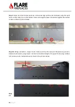
Step 7
: leave
4-6
”
inches between the left and right-side parts in order to be able to connect the
left side blowers-fans to the right-side blower fans using quick connectors as shown in the picture
below, then continue pushing until making the two parts closed to each other
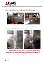
Step 8
:
1/2
″
gap has been filled with ceramic fiber paper between the left side part (B) the right-
side part (A) as shown in the picture below (
this step may already done
), then install the cover that
will cover the gap between the two parts.
Summary of Contents for Corner Right & Left 120
Page 65: ...65 P a g e COMBUSTIBLE FINISHING MATERIAL CLEARANCES ...
Page 71: ...71 P a g e EXAMPLES OF HEAT RELEASES ...
Page 77: ...77 P a g e ELECTRIC AND CONTROL ELECTRIC DIAGRAM SCREEN MV MV PV PV ...
Page 78: ...78 P a g e ELECTRIC DIAGRAM DOUBLE GLASS OR PV Double Glass Fan Plug No use MV MV PV PV ...
Page 80: ...80 P a g e ELECTRIC DIAGRAM PV SYSTEM Ports 49 47 are connected to J6 on fireplace main board ...


