48 |
P a g e
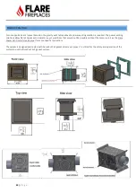
GAS VALVE ACCESS DOOR
The Flare Fireplace gas valve and control system is on an “
u
mbilical cord” that can be stretched
up to 50”
from the middle of
the fireplace and be put next to the access door location.
Do not place the gas valve or controls above the level of the burner.
If the fireplace is to sit low on the floor, the controls
must be placed outside the non-combustible zone or insulated from the heat from the fireplace.
The access door can be placed on any side of the fireplace, below the non-combustible line.
The use of
a 10”x10” access door is
highly recommended. If no access door is installed, it is possible to access the gas valve
from inside the fireplace by removing the glass.
The access door can also be used as a lower air intake for a double glass installation if it is perforated, and the opening
requirements are maintained.
The access door can be concealed in many ways such as HVAC vent cover, removable tile connected with Velcro straps and
more.
MANUAL GAS SHUT OFF
The installation of this appliance REQUIRES the implementation of a readily accessible Manual Gas Shut Off. Confirm
requirements of location and shut off type with your local codes.
NOTE: The Electronic Ignition of Flare Fireplaces DOES NOT satisfy the requirement for a Manual Gas Shut Off. See below for
example of Manual Gas Shut Offs.
LIQUID PROPANE USAGE IN A FLARE FIREPLACE
The Flare Fireplace can operate and fire using Natural Gas (Default) or Liquid Propane gas. If your installation requires the
fireplace to operate using Liquid Propane gas, make sure only to use the Flare Fireplaces liquid propane conversion kit.
Depending on your fireplace ignition system, LPG conversion kit may include the following:
•
LPG burner orifices
•
Pilot LPG orifices
•
SIT Valve LPG Conversion Kit
NEVER OPERATE A FIREPLACE ORDERED FOR NATURAL GAS WITH LP GAS UNLESS CONVERTED BY A
CERTIFIED FIREPLACE TECHNICIAN. USE ONLY FLARE FIREPLACE LP CONVERSION KIT. ALWAYS MEASURE
GAS INLET PRESSURE AND OUTLET PRESSURE POST CONVERSION
Summary of Contents for Corner Right & Left 120
Page 65: ...65 P a g e COMBUSTIBLE FINISHING MATERIAL CLEARANCES ...
Page 71: ...71 P a g e EXAMPLES OF HEAT RELEASES ...
Page 77: ...77 P a g e ELECTRIC AND CONTROL ELECTRIC DIAGRAM SCREEN MV MV PV PV ...
Page 78: ...78 P a g e ELECTRIC DIAGRAM DOUBLE GLASS OR PV Double Glass Fan Plug No use MV MV PV PV ...
Page 80: ...80 P a g e ELECTRIC DIAGRAM PV SYSTEM Ports 49 47 are connected to J6 on fireplace main board ...


