52 |
P a g e
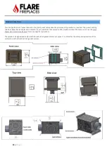
The following sizes MUST be maintained for the lower air intake:
For fireplaces sized
80
”
& 10
0”
–
vent area must be at least
100 square inches.
For fireplaces sized
60”
& 70
”
- vent area must be at least
70 square inches
.
For fireplaces sized
50”
and below - vent area must be at least
50 square inches.
For See Through and Room Definer fireplaces, the air intake requirements are
double
.
NOTE: Openings above for Heat Release and Air Intake are measured for open air space.
NOTE:
On all
See Through
and units the air intake must be doubled
To reduce you chase and double glass heat increase your heat release & air intake above listed minimum
The upper heat release may be a single or multiple opening if the total size of all the openings is at least the minimum
requirement listed above. They can be set at the front, back, sides or top.
The lower air intake may be a single or multiple opening if the total size of all the openings is at least the minimum requirement
listed above. They can be set at the front, back, or sides. It is recommended to place one long opening on below the long glass, to
allow for better distribution across all fans of air taken in from the bottom. If implementing side air intakes, make sure side
opening are not farther than 2 feet to the side of the fireplace.
Lower air intake is REQUIRED for Double Glass and units with an optional blower kit.
Size
Vent Size
Units Size
Flare 120
2 x 5x8
2 x
70 square inches
–
Total 140
in
2
Flare 140
2 x 5x8
2 x
70 square inches
–
Total 140
in
2
Flare 160
2 x 5x8
2 x
100 square inches
–
Total 200
in
2
Flare 180
3 x 5x8
3 x
70 square inches
–
Total 210
in
2
Flare 200
2 x 5x8
2 x
100 square inches
–
Total 200
in
2
Flare 210
3 x 5x8
3 x
70 square inches
–
Total 210
in
2
Flare 240
3 x 5x8
3 x
100 square inches
–
Total 300
in
2
Flare 280
4 x 5x8
4 x
70 square inches
–
Total 280
in
2
Flare 300
3 x 5x8
3 x
100 square inches
–
Total 300
in
2
Flare 320
4 x 5x8
4 x
100 square inches
–
Total 400
in
2
Flare 400
4 x 5x8
4 x
100 square inches
–
Total 400
in
2
Summary of Contents for Corner Right & Left 120
Page 65: ...65 P a g e COMBUSTIBLE FINISHING MATERIAL CLEARANCES ...
Page 71: ...71 P a g e EXAMPLES OF HEAT RELEASES ...
Page 77: ...77 P a g e ELECTRIC AND CONTROL ELECTRIC DIAGRAM SCREEN MV MV PV PV ...
Page 78: ...78 P a g e ELECTRIC DIAGRAM DOUBLE GLASS OR PV Double Glass Fan Plug No use MV MV PV PV ...
Page 80: ...80 P a g e ELECTRIC DIAGRAM PV SYSTEM Ports 49 47 are connected to J6 on fireplace main board ...


