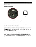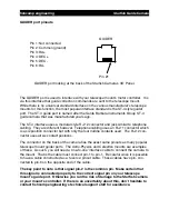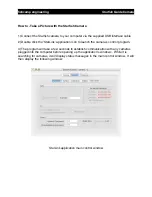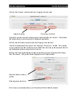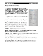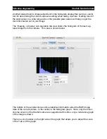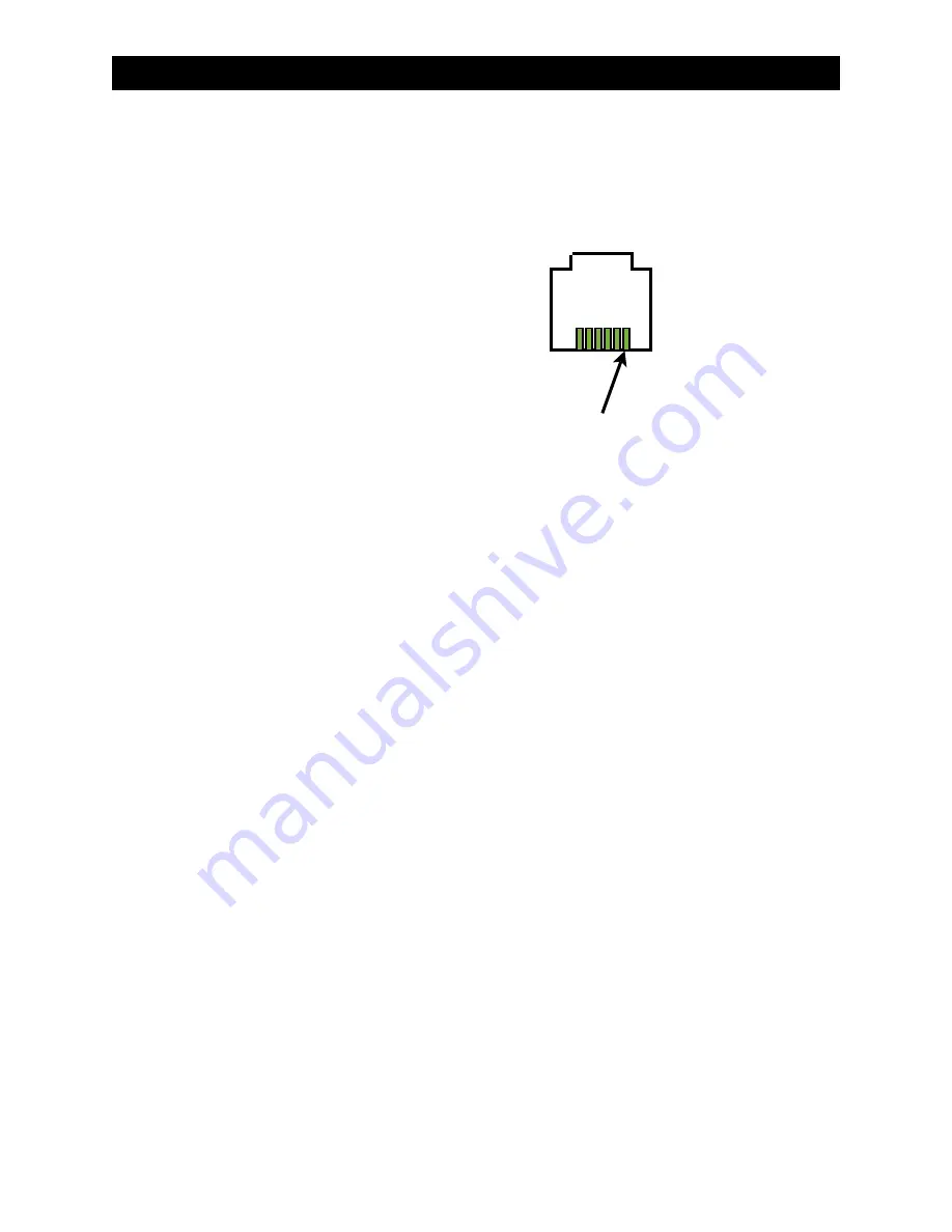
GUIDER port pinouts
GUIDER
Pin 1: Not connected
Pin 2: Common (ground)
Pin 3: RA+
Pin 4: DEC+
Pin 5: DEC-
Pin 6: RA-
Pin #1
GUIDER port looking at the back of the Starfish Camera
’
s I/O Panel.
The GUIDER port is used to interface with your telescope mount
’
s motor controller. It is
via this interface that guide correction commands are sent to the telescope mount.
While there is no universal standard interface on the various manufacturer
’
s telescope
mounts for this function, the most popular interface standard is the ST-4 style guider
port. The ST-4 guide port is named after the Santa Barbara Instruments Group ST-4
guide camera that was manufactured years ago.
The ST-4 interface uses a modular style RJ-12 connector and jack similar to telephone
cabling. They are different however. Telephone cabling uses an RJ-11 connector which
is a six position connector but with only the four middle contacts used. The RJ-12 con-
nector uses all six contact positions.
The connector on the back of the camera has the exact same pinouts as many popular
telescope mount guider ports. The Astro-Physics and Celestron mounts are examples
of these. As such, you will need a
‘
one-to-one
’
interface cable to connect the camera to
the mount. That is the cable must connect pin-1 to pin-1. Be careful since it is possible
to have a cable constructed as a
‘
reverse
’
pinout cable. These cables have pin- con-
nected to pin-6 on the opposite end of the cable.
The key point to note is that signal pin-2 is the common pin. Make certain that
this signal is connected properly to the correct signal pin on your telescope
mount
’
s guide port. Otherwise you run the risk of damage to the Starfish camera
or your mount
’
s controller. If there is an uncertainty about this, don
’
t hesitate to
contact fishcamp engineering
’
s technical support staff for assistance.
fishcamp engineering
Starfish
Guide Camera


