background image

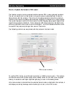
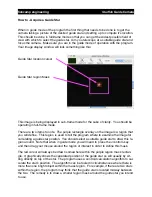
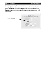
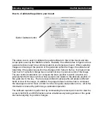
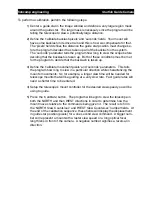
Two controls are provided.  The 

TEC Enable

 check box allows you to turn on and off 

the cooler.  The 

Set Temperature

 number field allow you to set the target temperature 

of the cooler.

The starfish camera can cool to a minimum of -12C below the ambient temperature. You 
can get an idea of what the ambient temperature is by looking at the 

Current Tempera-

ture

 reading before turning on the TEC cooler.  The camera has a built in thermistor for 

measuring the image sensor

s temperature.  It uses this to regulate the cooler

s tem-

perature.  The program displays the temperature measurement reading with an update 
approximately every 5 seconds.

So, for example, if the ambient temperature of the camera is 20°C, you could easily cool 
to 8°C by entering an 8 in the 

Set Temperature

 number field and checking the TEC en-

able check box.  

Along with the current temperature reading, the program will display the current power 
level set by the cooler controller.

The TEC cooler in the camera will generate a lot of heat when operating.  This heat is 
dissipated by the camera

s internal fan when operating.  This design works fine up to a 

point since at high power settings to the cooler, more heat will be generated than can 
easily be dissipated by the heat sink and fan.  It is recommended that you chose a tem-
perature setting that results in a power level setting of 75% or lower so that there is 
plenty of headroom for the cooler regulator to operate.

fishcamp engineering

Starfish

 Guide Camera

Summary of Contents for Guide Camera

Page 1: ...Starfish Guide Camera User s Manual fishcamp engineering Starfish Guide Camera ...
Page 2: ...with the Starfish Camera 12 How to Adjust the Image Display 14 How to Work with a sub frame of the image sensor 18 How to Capture Calibration data for the image sensor 20 How to Auto Calibrate Images 25 How to Save images to Disk 27 How to Operate the Camera s TEC cooler 29 Operating as a Guide Camera 31 How to Setup the camera for guiding 31 Hardware interface checks 31 How to Setup Guiding mode ...

Page 3: ...ce Guiding Guide Star Data tab view 41 Reference Guiding Guide Star Error tab view 43 Reference Guider Parameters tab view 44 Reference Guider Images tab view 47 Reference Guide History Window 48 Reference Imaging Windows 49 Reference Imaging Filter Wheel tab view 49 Troubleshooting 50 Autoguiding 50 fishcamp engineering Starfish Guide Camera ...
Page 4: ...ontainer if possible and the RMA number must be clearly marked on the outside of the package The information provided in this manual is believed to be correct however fishcamp engineering assumes no responsibility for errors contained within The software programs are provided as is without warranty of any kind either expressed or implied No other warranty is expressed or implied Fishcamp engineeri...

Page 5: ...Introduction fishcamp engineering Starfish Guide Camera ...
Page 6: ...ovided by the USB interface TEC PWR connector this connector provides power for the TEC cooler in the cam era 12VDC with center pin positive RS 232 connector this is a standard serial data connector for interfacing with exter nal devices such as filer wheels or motorized focusers Status LED s these indicators provide visual feedback on the camera s operation The status indicator will blink when th...

Page 7: ... a six position connector but with only the four middle contacts used The RJ 12 con nector uses all six contact positions The connector on the back of the camera has the exact same pinouts as many popular telescope mount guider ports The Astro Physics and Celestron mounts are examples of these As such you will need a one to one interface cable to connect the camera to the mount That is the cable m...

Page 8: ...ware program that runs on the USB interface processor in the Starfish camera It is downloaded to the camera at startup time from the host computer 4 Guider_mono_revx_intel srec firmware program that executes on the image processor in the Starfish camera It is also downloaded to the camera from the host computer at startup time All of these files are stored in the C Program Files fishcamp install d...

Page 9: ...i rectory on your computer 2 Guider_mono_revx_intel srec Guider_mono_revx_ppc srec these files are firmware programs that execute on the image processor in the starfish camera It is also downloaded to the camera from the host computer at startup time The files are copied to the Library Application Support fishcamp directory on your computer Only one of these files are used depending upon which pro...

Page 10: ...s Sub operation view tabs This is the window where you will control most of all the operations of the starfish cam era It has a set of tabbed views at the top of the window that correspond to the three modes of operation The following three modes are presently defined Operation Tabs Guiding tabbing to this view will allow you to operate the Starfish camera as a telescope mount guide camera Imaging...

Page 11: ...low the Operation Tabs are a set of Sub operation Tabs These allow you to bring up views that display more detailed information applicable to the currently selected top level view fishcamp engineering Starfish Guide Camera ...
Page 12: ...mera s control program 3 The program will take a few seconds to establish communication with any cameras plugged into the computer before opening up the application s windows While it is searching for cameras it will display status messages in the main control window It will then display the following window StarLink application main control window fishcamp engineering Starfish Guide Camera ...
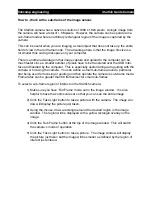
Page 13: ...te time value in the Exposure Time secs txt field This number is any number from 0 001 to 300 0 1ms to 5 Minutes and sets up the exposure time for any subsequent pictures taken with the camera 8 Press the Take Light Frame s button to start the exposure and upload the image from the camera The picture will be displayed in the image window Click this button to take a picture Enter exposure time here...

Page 14: ...es in luminance below that value are considered noise and get a noise reduction treatment by locally blurring Changes above the threshold value are considered edges so they are sharpened Sharpness increases the image detail by sharpening Gamma Adjusts midtone brightness This is a nonlinear adjustment that effectively changes the slope of the transition between black and white Exposure Adjusts the ...

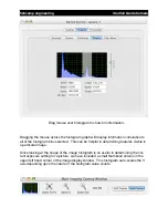
Page 15: ...n tab view shows the histogram of the last cap tured image from the camera This view is shown below The bottom of the window shows some statistical information about the RAW image data of the current picture In the center is the histogram graph Since only the mono chrome version of the Starfish camera is supported at this time only a luminance graph of the image is drawn There is a zoom slider on ...

Page 16: ...ing features visible in a particular image Since looking at the shape of the image histogram is so useful in determining the cor rect exposure setting for a picture we have included a small thumbnail version in the upper left hand corner of the image display window This histogram auto scales the Y axis depending upon the nature of the histogram value counts fishcamp engineering Starfish Guide Came...

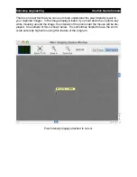
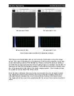
Page 17: ...you hold down the option key while mousing around the image the intensity of the pixel under the mouse will be dis played An example of this is shown below It is sometimes helpful to have the zoom scale set pretty high when using this feature of the program Pixel intensity display attached to cursor fishcamp engineering Starfish Guide Camera ...
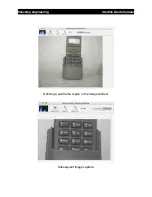
Page 18: ...mera You can define a small sub frame around a particular star being used for focusing or guiding and then operate the camera in sub frame mode Frame rates can be greater than 60 frames sec for small sub frames To select a sub frame region of interest on the Starfish camera 1 Make sure you have Full Frame mode set in the image window It is also helpful to have the zoom scale set so that you can se...

Page 19: ...Defining a sub frame region in the image window Subsequent image capture fishcamp engineering Starfish Guide Camera ...
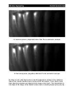
Page 20: ...is not related to the actual amount of light falling on the sensor Dark frames are taken with the lens cap covering the camera so that no light is falling on the sensor dur ing the exposure That is why they are called Dark Frames Dark current builds up over the duration of an exposure being taken by the camera Long duration exposures will accumulate more dark current in the pixel wells than a pict...

Page 21: ...s somewhere around 33 of maximum as shown by the histogram display Flat frames will record the intensity varia tion of the pixels across the frame of the entire imaging system This includes the opti cal system as well as that of the camera itself Once the three calibration reference frames are acquired they can be used to adjust any subsequent pictures taken with the camera such that the resulting...

Page 22: ...ere will be some time dependent variation in the calibration frames from random electrical noise sources within the camera This is due to some basic physical properties associated with the image sensor itself This characteristic is not unique to the design of the Starfish camera but is something that all astro cameras fishcamp engineering Starfish Guide Camera ...
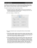
Page 23: ...calibration frame by specifying the number of bias frames to take and then pressing the Take Bias button The specified number of Bias frames will be taken and then median combined into a Master Bias frame that will be used for all subsequent image calibration operations 5 Take a Dark calibration frame by specifying the number of dark frames to take and entering the exposure duration to use Make su...

Page 24: ...ting before taking the Dark frames 6 Setup for the flat frame exposures by evenly illuminating the image sensor on the camera and selecting an appropriate exposure setting It is best to select an exposure time that puts most of the pixels in the histogram graph at the 1 3 point between black and white 7 Enter the number of frames to average for the Master Flat Frame and then press the Take Flat bu...

Page 25: ...party image proc essing applications There are several good programs to chose from including pro grams dedicated to Astro photography as well as general purpose image processing applications like Photoshop An easier way to do this is to let the StarLink program do it automatically for you as it captures images from the camera This is called On the fly Calibration The tab view Imaging Summary has s...

Page 26: ...that a valid calibration frame has been acquired by the camera before allowing you to specify the operation to be performed If for in stance you have not collected a flat frame the Flat Field check box will be disabled and the red warning text will be displayed reminding you to perform the Flat Frame ac quisition Changing the mode of the camera from Full frame to Sub frame operation or changing th...

Page 27: ...his kind of im age is a version of the camera RAW image with the calibration frames applied Only the calibration operations specified by the check boxes in the Imaging Summary view will be applied You can specify either or both image file types to be generated by the program Any images stored will be TIFF file types Images are saved right after being downloaded from the camera Pressing the Set Sav...

Page 28: ...prefix _RAWlight_ tiff prefix _CALlight_ tiff So for example if you specify a file name prefix of M51 and capture two pictures with the camera the following image files are saved M51_RAWlight_0 tiff M51_CALlight_0 tiff M51_RAWlight_1 tiff M51_CALlight_1 tiff fishcamp engineering Starfish Guide Camera ...
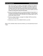
Page 29: ...long exposures the dark noise will be a significant noise source in the final images It is recommended that the cooler be used for any exposures longer than about 15 seconds The following controls are associated with the camera s internal cooler TEC Cooler controls To use the TEC cooler you will need to provide a 12VDC power source The camera comes with both an AC power supply and a battery cable ...

Page 30: ...o for example if the ambient temperature of the camera is 20 C you could easily cool to 8 C by entering an 8 in the Set Temperature number field and checking the TEC en able check box Along with the current temperature reading the program will display the current power level set by the cooler controller The TEC cooler in the camera will generate a lot of heat when operating This heat is dissipated...

Page 31: ... will need to attach the Starfish GUIDER port to the guide port on your telescope mount See the hardware installation section of this manual for more information Verify that the starfish camera is properly interfaced to your mount Open the camera control application and click on the Telescope Control window Press one of the manual slew control buttons in the window and if everything is OK the tele...

Page 32: ... program can be used together but a given camera can be as signed as either your primary imaging camera or your guide camera It can not do both This means that you would have to have two cameras to perform both imaging and guiding Guiding Tab Before you can begin guiding you will have to specify the camera to use under the Guiding Camera sub view tab Select your guide camera in this view fishcamp ...

Page 33: ...tinuously take pictures with the camera The exposure time and seconds between pictures can be set in the Camera sub operation tab view and determine the repetition rate that the pictures will be taken fishcamp engineering Starfish Guide Camera ...
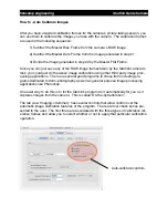
Page 34: ...ine This region is used to tell the program where to examine the image for calculating a guide star position You should select a suitable guide star to draw this re gion around Note that when in guide mode you will need to press the control key and then drag your mouse around the region of interest in order to define this mask The red cursor will always be drawn somewhere within the purple region ...

Page 35: ...ntensity Threshold slider This slide selects the threshold level of intensity that the program assumes is part of the guide star A higher level setting will be useful in cases where there is a high background noise level in the captured image A setting of somewhere around 75 is recommended Threshold slider fishcamp engineering Starfish Guide Camera ...

Page 36: ...f the image The star centroid calculation can compute the star s position to within a fraction of a pixel element but it does not know how a pixel s size relates to the absolute position of the guide star in the sky That is because different optical paths will produce different fields of view of the image In addition the program does not know how to command the telescope mount to move in order to ...

Page 37: ...rameters This tells the program how long to slew in a particular direction while characterizing the mount s movements So for example a longer slew time will be needed for telescope mounts that will be guiding at a very slow rate Fast guide rates will need a shorter time to be entered 4 Setup the telescope s mount controller for the desired slew speed you will be using to guide 5 Press the Calibrat...

Page 38: ...d above you can start guiding by simply checking the Auto Guide Enable check box The system will start tracking the guide star at that point and present a log and graph of guide performance in the Guide History window fishcamp engineering Starfish Guide Camera ...
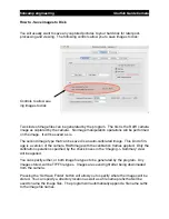
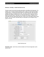
Page 39: ...the other tab views of the window A screen dump of this view is shown below The following controls and fields are presented in this view Auto Guide Enable check box this control allows the user to turn on off the guide corrections to the mount Only when this check box is checked will guide corrections be sent to the telescope mount You should have previously calibrated the auto guider be fore enab...

Page 40: ...ictures taken by the guide camera This value can be a minimum of 0 001 second up to a reasonable value of perhaps a couple of seconds The increment is 0 001 seconds Guider Aggressiveness sliders these controls allow you to specify how guide calcu lations are computed After every guide star picture is taken the program computes the ideal mount correction that would need to get sent to the mount to ...

Page 41: ...The mask is used in order to keep the algorithm from getting confused when more than one bright star is captured in the im ages by the guide camera Normally you would define this region by drawing a box around the guide star while holding down the control key in the Guide Camera Image Window You can however manually enter the coordinates of the rectangle s corner points in this view Guide Star Dat...

Page 42: ... is the pixel intensity level of the brightest pixels under the guide star Num significant Pixels the total number of pixels that are above the Star intensity threshold level This number should be at least a dozen or so pixels for a good guide star position calculation If too low then a lower setting on the Pixel intensity threshold slider or a longer integration time should be set Pixel intensity...

Page 43: ...as the current guide star error from that target position is shown This is calculated from the last image taken from the guide camera Also shown is the first and second derivative of the guide star position These corre spond to the drift speed and drift acceleration status boxes in the view The Guide Star RMS error is calculated over the previous 100 samples of the guide star position fishcamp eng...

Page 44: ...he calibration operation the telescope will be commanded to slew in both the NORTH and WEST directions in order to characterize the response of the telescope system to guide correction commands that are sent from the guider Pressing the Abort button will stop sending any slewing commands to the telescope mount Auto Guide Enable checking this box will start the operation of calculating guide star p...

Page 45: ...e states are error conditions and will be dis played in RED The current state of the state machine is always displayed in this text field NORTH Slew Counts sec during the calibrate routine the number of pixels of position change per second observed of the guide star while slewing in the NORTH direction is reported here WEST Slew Counts sec during the calibrate routine the number of pixels of posit...

Page 46: ...e precedence to this parameter if it is longer Minimum move guide corrections are not sent to the mount unless they are at least big enough to exceed the value entered here Maximum move guide corrections larger than this are never sent to the mount fishcamp engineering Starfish Guide Camera ...
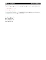
Page 47: ...formance or time lapse image sequences This view allows you to specify the timing of the images to save To enable the save operation you need to check the Save Guider Images to Disk check box and specify a frequency of the images that will be stored Intermediate images that are captured are not stored Only images captured after the Frequency of Save timer has expired are saved Each time an image i...

Page 48: ...er right hand corner of the window There are two sets of controls in the window that affect the view of the graphical data The first is a set of check boxes that allow the user to specify which of the four parame ters are graphed Any or all of them can be shown by checking or un checking their re spective check box The second control that is available to the user is the zoom slider that allows you...

Page 49: ...tartup If a supported wheel is found the following tab view will be displayed For each filter position you can enter a text string describing the characteristics of the filter installed The descriptions entered will be saved in a user preferences file for the program Basic filter selection is accomplished by selecting the desired filter position and then pressing the Set Wheel Filter Position butt...

Page 50: ...eral readings be fore using the guide star position That is under the of readings to average field Next I would turn on guiding but turn OFF guide corrections to see the guide star drift graph in the Guide history window Without guide corrections you will see immediate drift depending upon the quality of your mount and the accuracy of your polar alignment The thing to look for is the smoothness of...

Reviews: