background image

OPERATION 

FIREPOWER 160 S

Manual 0-5371 

4-3 


   Operation

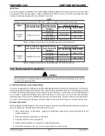
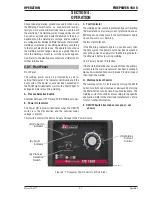
20 Amp Outlet
The mains power 20 Amp circuit breaker or fuse should not trip at this Weld Current value when STICK welding. 
The environmental conditions that may cause the mains power 20 Amp circuit breaker or fuse to trip are:

a)  High ambient temperature

b)  Worn parts in circuit breaker

c)  Using an extension cable

d)  Low line mains power voltage

Output Scale for 115V 

The inside number scale identifies the available output weld current for STICK or LIFT TIG weld modes.

STICK Mode: 

 Identifies the STICK weld point for 15 Amp outlet.


    Identifies the STICK weld point for 20 Amp outlet.


Exceeding these points will cause nuisance tripping of the circuit breaker or fuse.

LIFT TIG Mode: A 15 Amp outlet is capable of supplying enough input power for all LIFT TIG output weld current 

values. 

Nuisance tripping should not occur on a 15 Amp outlet.
Output Scale for 208/230V
The outside number scale identifies the available output weld current for STICK or LIFT TIG weld modes. 
Nuisance tripping should not occur on a 50A 208/230V outlet for both STICK & LIFT TIG Modes.

Art#: A-12713 

15 Amp Outlet

20 Amp Outlet

Output Scale for 115V

Output Scale for 230V

Figure 4-3 Current Control (US Version)

Summary of Contents for TIG 160S

Page 1: ...Service Manual A 12705 Firepower TIG 160S Inverter Arc Welder English Canadien Français Americas Español Revision AA Issue Date September 8 2015 Manual No 0 5371 www firepoweronline com ...

Page 2: ...ur competition through market leading innovation and truly dependable products that will stand the test of time We strive to enhance your productivity efficiency and welding performance enabling you to excel in your craft We design products with the welder in mind delivering advanced features durability ease of use and ergonomic comfort Above all we are committed to a safer working environment wit...

Page 3: ... MO 63017 USA www firepoweronline com Copyright 2014 by Victor Technologies Inc All rights reserved Reproduction of this work in whole or in part without written permission of the publisher is prohibited The publisher does not assume and hereby disclaims any liability to any party for any loss or damage caused by any error or omission in this Manual whether such error results from negligence accid...

Page 4: ...ent 3 5 3 04 Location 3 5 3 05 Electrical Input Connections 3 6 3 06 Electromagnetic Compatibility 3 8 3 07 Volt Ampere Curves 3 10 SECTION 4 OPERATION 4 1 4 01 Front Panel 4 1 4 02 Setup for Welding 4 2 4 03 Welding Current Control Explanation US Version 4 2 4 04 Welding Current Control Explanation UK Version 4 4 4 05 STICK SMAW Setup 4 5 4 06 LIFT TIG GTAW Setup 4 6 4 07 Firepower Regulator US V...

Page 5: ... Panel Operator Interface Circuit Board PCB3 Removal 7 6 7 05 Back Panel Removal 7 8 7 06 Power Switch S1 and Power Cord Removal 7 10 7 07 Base Panel Removal 7 11 SECTION 8 ASSEMBLY PROCEDURES 8 1 8 01 Installing Base Panel and Main PCB1 8 1 8 02 Installing Back Panel 8 2 8 03 Installing Front Panel 8 4 8 04 Installing Main Control Panel and Clear Cover Sheet 8 6 8 05 Installing Case 8 7 SECTION 9...

Page 6: ...This Page Intentionally Blank ...

Page 7: ...y in place WARNING ARC RAYS can burn eyes and skin NOISE can damage hearing Arc rays from the welding process produce intense heat and strong ultraviolet rays that can burn eyes and skin Noise from some processes can damage hearing 1 Wear a welding helmet fitted with a proper shade of filter see ANSI Z49 1 listed in Safety Standards to protect your face and eyes when welding or watching 2 Wear app...

Page 8: ... that welding sparks and hot materials from welding can easily go through small cracks and openings to adjacent areas 5 Watch for fire and keep a fire extinguisher nearby 6 Be aware that welding on a ceiling floor bulkhead or partition can cause fire on the hidden side 7 Do not weld on closed containers such as tanks or drums 8 Connect work cable to the work as close to the welding area as practic...

Page 9: ...ore fueling If possible check and add fuel to cold engine before beginning job 4 Do not overfill tank allow room for fuel to expand 5 Do not spill fuel If fuel is spilled clean up before starting engine WARNING MOVING PARTS can cause injury Moving parts such as fans rotors and belts can cut fingers and hands and catch loose clothing 1 Keep all doors panels covers and guards closed and securely in ...

Page 10: ...istant shields or other approved material to protectnearbywallsorunprotectedflooringfromsparksand hot metal 4 Keep an approved fire extinguisher of the proper size and type in the work area Inspect it regularly to ensure that it is in proper working order Know how to use the fire extin guisher 5 Move combustible materials away from the work site If you can not move them protect them with fireproof...

Page 11: ...this condition immediately 6 Momentarily open and close called cracking the cylinder valve to dislodge any dust or dirt that may be present in the valve CAUTION When cracking the cylinder valve DO NOT stand directly in front of the cylinder valve Always perform cracking in a well ventilated area If an acetylene cyl inder sprays a mist when cracked let it stand for 15 minutes Then try to crack the ...

Page 12: ...quency Negative Positive Direct Current DC Protective Earth Ground Line Line Connection Auxiliary Power Receptacle Rating Auxiliary Power Art A 04130_AB 115V 15A t t1 t2 X IPM MPM t V Fuse Wire Feed Function Wire Feed Towards Workpiece With Output Voltage Off Preflow Time Postflow Time Spot Time Spot Weld Mode Continuous Weld Mode Press to initiate wirefeed and welding release to stop Purging Of G...

Page 13: ...STATIC ESD can damage PC boards Put on grounded wrist strap BEFORE handling boards or parts Use proper static proof bags and boxes to store move or ship PC boards WARNING FIRE OR EXPLOSION hazard Do not place unit on over or near combustible surfaces Do not service unit near flammables WARNING FLYING METAL or DIRT can injure eyes Wear safety glasses with side shields or face shield during servicin...

Page 14: ...rvicing this unit Consult the Owner s Manual for welding safety precautions Use only genuine replacement parts from the manufacturer 1 06 EMF Information Considerations About Welding And The Effects Of Low Frequency Electric And Magnetic Fields Welding current as it flows through welding cables will cause electromagnetic fields There has been and still is some concern about such fields However aft...

Page 15: ...SAFETY INSTRUCTIONS AND WARNINGS FIREPOWER 160 S Manual 0 5371 1 9 Safety Instructions and Warnings Notes ...

Page 16: ...FIREPOWER 160 S SAFETY INSTRUCTIONS AND WARNINGS Safety Instructions and Warnings 1 10 Manual 0 5371 This Page Intentionally Blank ...

Page 17: ... using a fork lift vehicle secure the unit on a proper skid before transporting 2 01 How to Use This Manual This Manual usually applies to the part numbers listed on page i To ensure safe operation read the entire manual including the chapter on safety instructions and warnings Throughout this manual the word WARNING CAUTION and NOTE may appear Pay particular attention to the information provided ...

Page 18: ...FIREPOWER 160 S INTRODUCTION Introduction 2 2 Manual 0 5371 Notes ...

Page 19: ... cycle at 160 amperes and 26 4 volts This means that it has been designed and built to provide the rated amperage 160A for 3 minutes i e arc welding time out of every 10 minute period 30 of 10 minutes is 3 minutes During the other 7 minutes of the 10 minute period the Welding Power Source must idle and be allowed to cool 0 20 40 60 80 100 120 0 20 40 60 80 100 120 AMPS Duty Cycle percentage 40ºC 1...

Page 20: ...tion 3 2 Manual 0 5371 0 20 40 60 80 100 120 0 20 40 60 80 100 120 140 AMPS Duty Cycle percentage 110VAC Input Stick Lift TIG Art A 10197 3 5 17 9 QSXW 00 67 7 7 XW FOH HOGLQJ XUUHQW 036 6DIH 2SHUDWLQJ 5HJLRQ Art A 10198_AB Figure 3 2 160S Duty Cycle UK Version ...

Page 21: ... Power Source Output Terminal Type Heavy Duty DinseTM 50 Classification Protection Class IP23S Standards EN 60974 1 EN50199 Cooling Method Fan Cooled Dimensions and Weight Welding Power Source Mass 17 4 lb 7 9 kg Welding Power Source Dimensions Height x Width x Depth H 9 0 x W 5 3 x D 15 5 H230mm x W135mm x D393mm The recommended time delay fuse or circuit breaker size is 30 amp An individual bran...

Page 22: ...0A 35 Rated Output for LIFT TIG GTAW Welding 15V 125A 50 16 4V 160A 40 Duty Cycle 20 125A 35 160A Welder Type Inverter Power Source Output Terminal Type Heavy Duty DinseTM 50 Classification Protection Class IP23S Standards EN 60974 1 EN50199 Cooling Method Fan Cooled Dimensions and Weight Welding Power Source Mass 7 9 kg 17 4 lb Welding Power Source Dimensions Height x Width x Depth H230mm x W135m...

Page 23: ...umidity or perspiration considerably reduces the skin resistance of the human body and the insulation properties of accessories Environments with increased hazard of electric shock do not include places where electrically conductive parts in the near vicinity of the operator which can cause increased hazard have been insulated 3 04 Location Be sure to locate the welder according to the following g...

Page 24: ...and inspection required The line disconnect switch provides a safe and convenient means to completely remove all electrical power from the welding power supply whenever necessary to inspect or service the unit Do not connect an input WHITE or BLACK conductor to the ground terminal Do not connect the ground GREEN conductor to an input line terminal Refer to Figure 3 3 1 Connect end of ground GREEN ...

Page 25: ...r Supply Primary Power Cable 120 120 V V 20A 1Ø 15A 1Ø 208 230V 50A 1Ø The Adapters enable connection to all these power outlets Art A 09862 Figure 3 3 Electrical Input Connections US Version Welding Power Supply Primary Power Cable Art A 10143 Figure 3 4 Electrical Input Connections UK Version ...

Page 26: ...ectromagnetic Compatibility may be required when this Welding Power Source is used in a domestic situation A Installation and Use Users Responsibility The user is responsible for installing and using the welding equipment according to the manufacturer s instructions If electromagnetic disturbances are detected then it shall be the responsibility of the user of the welding equipment to resolve the ...

Page 27: ... not be modified in any way except for those changes and adjustments covered in the manufacturer s instructions In particular the spark gaps of arc striking and stabilizing devices should be adjusted and maintained according to the manufacturer s recommendation 3 Welding Cables The welding cables should be kept as short as possible and should be positioned close together running at or close to the...

Page 28: ... shows maximum voltage and amperage output capabilities of welding power source Curves of other settings fall between curves shown 115VAC Input 036 VOLTS Stick Max lift TIG Max Art A 09843 230VAC Input 0 10 20 30 40 50 60 70 80 0 50 100 150 200 AMPS VOLTS Stick Max Lift TIG Max Art A 09844 Figure 3 5 Volt Ampere Curves US Version ...

Page 29: ...160 S Manual 0 5371 3 11 Safety and Installation OWDJH 9ROWV 9 QSXW 2XWSXW 9RO HOGLQJ XUUHQW PSV 00 67 7 7 Art A 10199_AB OWDJH 9ROWV 9 QSXW 00 67 2XWSXW 9RO HOGLQJ XUUHQW PSV 7 7 Art A 10200_AB Figure 3 6 Volt Ampere Curves UK Version ...

Page 30: ...FIREPOWER 160 S SAFETY AND INSTALLATION Safety and Installation 3 12 Manual 0 5371 Notes ...

Page 31: ...when using the Welding Power Source i e connect work lead di rectly to work piece and electrode lead is used to hold the electrode The welding current range values should be used as a guide only Current delivered to the arc is dependent on the welding arc voltage and as welding arc voltage varies between different classes of electrode welding current at any one setting would vary according to the ...

Page 32: ...en different classes of electrodes welding current at any one setting would vary according to the type of electrode in use The operator should use the welding current range values as a guide then fine tune the welding current to suit the application WARNING Before connecting the work clamp to the work and inserting the electrode in the electrode holder make sure the Primary power supply is switche...

Page 33: ...ld modes STICK Mode Identifies the STICK weld point for 15 Amp outlet Identifies the STICK weld point for 20 Amp outlet Exceeding these points will cause nuisance tripping of the circuit breaker or fuse LIFT TIG Mode A 15 Amp outlet is capable of supplying enough input power for all LIFT TIG output weld current values Nuisance tripping should not occur on a 15 Amp outlet Output Scale for 208 230V ...

Page 34: ...ICK or LIFT TIG weld modes STICK Mode Identifies the STICK weld point for 32 Amp outlet Exceeding these points will cause nuisance tripping of the circuit breaker or fuse LIFT TIG Mode A 32 Amp outlet is capable of supplying enough input power for all LIFT TIG output weld current values Nuisance tripping should not occur on a 32 Amp outlet Output Scale for 230V The outside number scale identifies ...

Page 35: ...and the electrode holder cable to the positive output terminal NOTE This set up is known as DC Electrode Posi tive or reverse polarity Please consult with the stick electrode manufacturer for specific polarity recommendations 3 Connect the work clamp to your workpiece 4 Plug the power cable into the appropriate outlet and turn the switch to the ON position The power L E D light should illuminate 5...

Page 36: ...G welding on most materials such as steel and stainless steel 3 Using a secured Argon cylinder slowly crack open then close the cylinder valve while standing off to the side of the valve This will remove any debris that may be around the valve regulator seat area 4 Install the regulator for details of Firepower regula tor please refer to 4 07 and tighten with a wrench 5 Connect the gas hose to the...

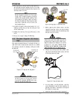
Page 37: ...nd other applications LOW PRESSURE GAUGE DELIVERY HIGH PRESSURE GAUGE SUPPLY INLET CONNECTION OUTLET CONNECTION PRESSURE ADJUSTING SCREW A 12435 Figure 4 7 Firepower CS Regulator WARNING Use the regulator for the gas and pressure for which it is designed NEVER alter a regu lator for use with any other gas Art A 12436 Figure 4 8 Regulator to Cylinder Valve 1 Before opening the cylinder valve turn t...

Page 38: ... using Argon set at a flow rate of around 20 CFH You will need to use a TIG torch that has a gas valve and is properly adjusted Tungsten Collet Collet body nozzle and back cap 1 Attach the TIG torch lead to the terminal of the power supply 2 Attach the work lead with ground camp to the terminal of the power source and your work piece NOTE About tungsten selection for this power supply a 2 Thoriate...

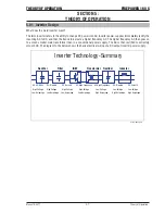
Page 39: ...ormer than in a conventional power supply The AC is then rectified to extremely smooth DC The diagram to the below shows the basic electrical wiring of a DC output inverter power supply AC High Frequency AC High Frequency Art A 09846_AB High Amperage High Amperage High Amperage Low Amperage Low Amperage Low Amperage Low Amperage High Voltage High Voltage High Voltage Low Voltage Low Voltage Low Vo...

Page 40: ...FIREPOWER 160 S THEORY OF OPERATION Theory of Operation 5 2 Manual 0 5371 Notes ...

Page 41: ...rted between pin 1 and 2 or pin 2 and 3 of J3 connector on Control PCB2 if it is shorted replace Control PCB2 4 If above is fine replace Main Power PCB1 No Open Circuit voltage 1 Check process switch on front panel to determine whether it is functioning properly 2 Check the Bus voltage on Main Power PCB1 It should read 385VDC see 6 05 3 Turn SW1 to Off position and disconnect Input from Primary In...

Page 42: ... working on unit Significant DC voltage can remain on capacitors after unit is Off Wait until all front panel LED s are off before removing case Check DC bus voltage according to Section 6 07 after removing case Before troubleshooting or applying power to unit complete the following checks to avoid causing further damage 6 03 Tools Needed for Troubleshooting and Servicing Art A 09849 ...

Page 43: ...71 6 3 Troubleshooting 6 04 Case Removal Read and follow safety information in Section 6 02 before proceeding 1 Cover 2 Screws Remove the 4 screws 2 on each side of the unit Remove screws from both the Front and Rear Panels A 12725 2 1 2 A 12727 ...

Page 44: ...refully lift the case to access and remove the screw which connects the ground wire to the cover 3 Art A 09851_AC 6 05 Clear Cover Sheet Removal Read and follow safety information in Section 6 02 before proceeding 1 Clear protective sheet Take out clear protective sheet 1 Art A 09852 ...

Page 45: ...TROUBLESHOOTING FIREPOWER 160 S Manual 0 5371 6 5 Troubleshooting 6 06 Pre Power Check Measure Points for following tests 1 3 4 9 2 12 11 8 13 14 15 16 7 6 5 10 17 18 Art A 09853 ...

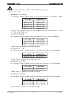
Page 46: ...ive Probe Negative Probe Measure Point 6 Measure Point 5 Measure Point 8 Measure Point 7 If reading is out of voltage drop range replace main board 3 Measurement of PFC IGBT Set multimeter to diode mode Diode voltage drop reading should be in the range of 0 200 0 600V Positive Probe Negative Probe Measure Point 9 Measure Point 10 If reading is out of voltage drop range replace main board 4 Measure...

Page 47: ... Point 17 Measure Point 18 If reading is not 4ohms within 5 replace Resistor R1 7 Power Switch S1 Continuity Check 1 Art A 09854_AB Read and follow safety information in Section 6 02 before proceeding 1 ON OFF switch Place ON OFF switch in ON position Measure the two top terminals for continuity Then check the two bottom terminals for same result If either test is faulty replace ON OFF switch ...

Page 48: ...age reading with multimeter before inspection Set multimeter to DC volt age mode Read and fo llow safety information in Section 6 02 before proceeding 1 DC Positive 2 DC Negative Check and make sure input capacitors are discharged and voltage is near 0 VDC When powered up voltage should read 385 VDC 2 1 Art A 09856 ...

Page 49: ...SHOOTING FIREPOWER 160 S Manual 0 5371 6 9 Troubleshooting 6 08 Installing Clear Cover Sheet Read and follow safety information in Section 6 02 before proceeding Replace the clear protective sheet Art A 09857 ...

Page 50: ...FIREPOWER 160 S TROUBLESHOOTING Troubleshooting 6 10 Manual 0 5371 6 09 Waveforms for Section 6 10 A OCV Waveform of Transformer primary Art A 09858 ...

Page 51: ...OTING FIREPOWER 160 S Manual 0 5371 6 11 Troubleshooting B Output 160A 26 4V transformer primary waveform under input 230VAC Art A 09859 C Output 160A 26 4 V output voltage waveform under input 230VAC Art A 09860 ...

Page 52: ...160 S TROUBLESHOOTING Troubleshooting 6 12 Manual 0 5371 D Output 110A 24 4V transformer primary waveform under input 115VAC Art A 09894 E Output 110A 24 4V output voltage waveform under input 115VAC Art A 09895 ...

Page 53: ...7 J3 8 J4 6 J4 5 J4 4 J4 3 J4 2 J4 1 15V POT WIPER Fault Process Switch GND N A J7 2 J7 1 J8 1 J8 2 GND 24V J7 3 15V GND RED BLACK J9 1 J9 2 J1 2 J1 1 RED Main Power PCB1 Control PCB2 Front Panel PCB3 J6 1 J6 2 J6 3 J6 4 GND 15V 15V Current Feedback 3 J 7 J 8 J J 6 J1 J4 CONNECTOR LAYOUT DIAGRAM JC OT T U O M I B F I J F ON 1 VRD ON OFF FAN PFC CIRCUIT MBIN WVIN RED BLACK J11 5 J11 4 J11 3 J11 2 J...

Page 54: ...FIREPOWER 160 S TROUBLESHOOTING Troubleshooting 6 14 Manual 0 5371 Notes ...

Page 55: ...0 S Manual 0 5371 7 1 Disassembly Procedure 7 01 Safety Precautions for Disassembly Read and follow safety information in Section 6 02 before proceeding Unplug unit before beginning Disassembly procedure SECTION 7 DISASSEMBLY PROCEDURE ...

Page 56: ...w Remove 4 screws from Control panel 2 Control PCB2 3 Disconnect J5 harness from J5 connector 4 Disconnect J1 harness from J1 connector 5 Disconnect J8 harness from J8 connector 6 Disconnect J7 harness from J7 connector 7 Disconnect J3 harness from J3 connector 8 Disconnect J4 harness from J4 connector 9 Disconnect J6 harness from J6 connector Ensure to unplug all harness from the main control PCB...

Page 57: ...SASSEMBLY PROCEDURE FIREPOWER 160 S Manual 0 5371 7 3 Disassembly Procedure Control PCB2 3 J 7 J 8 J J6 J1 J4 CONNECTOR LAYOUT DIAGRAM JC OT T U O M I B F I J F ON 1 VRD ON OFF MBIN WVIN J5 Art A 09847_AB ...

Page 58: ...follow safety information in Section 6 02 before proceeding with disassembly 1 Power supply output Negative 2 Power supply output Positive 3 Output terminal bolts Unscrew power supply output terminal bolts using 17mm wrench 4 Front Panel PCB3 harness Disconnect the harness from Front Panel PCB3 A 12728 2 1 3 Art A 09865 ...

Page 59: ...DISASSEMBLY PROCEDURE FIREPOWER 160 S Manual 0 5371 7 5 Disassembly Procedure 4 Art A 09866 ...

Page 60: ...with disassembly 1 PROCESS Selector Switch Boot Remove the rubber boot from the PROCESS Selector switch by turning the retaining nut counter clockwise 2 WELD CURRENT Control Knob Remove the WELD CURRENT KNOB by loosening the set screw 3 WELD CURRENT control mounting nut Remove mounting nut 4 Front Panel PCB3 Remove the Front Panel PCB3 from the panel 5 Panel mounting screw Remove screw A 12729 1 2...

Page 61: ...DISASSEMBLY PROCEDURE FIREPOWER 160 S Manual 0 5371 7 7 Disassembly Procedure Art A 09868 4 5 Art A 09870 ...

Page 62: ...sassembly 1 ON OFF switch 2 Wire from Main PCB1 Disconnect the two wires from PCB1 3 Rear panel mounting SCREW Remove screw holding rear panel to chassis 4 Ground wire screw Disconnect Input cord ground wire from Main Power PCB1 using a 1 4 wench 5 Disconnect harness from J8 connector on Control PCB2 and carefully lift the wire free from the unit 1 2 Art A 09871 3 Art A 09872 ...

Page 63: ...DISASSEMBLY PROCEDURE FIREPOWER 160 S Manual 0 5371 7 9 Disassembly Procedure 4 Art A 09873 5 Art A 09876 ...

Page 64: ...1 2 SW1 locking tabs Squeeze the locking tabs and push SW1 out from the rear panel 3 Input Power Cord 4 Strain relief screws Remove the two 2 screws from the strain relief 5 Input Power Cord ground wire filter Cut the tie wrap and remove the magnet from the ground wire 6 Pull the Input Power Cord out It may be necessary to use a flat blade screw driver against the strain relief tabs prying outward...

Page 65: ... Manual 0 5371 7 11 Disassembly Procedure 7 07 Base Panel Removal Read and follow safety information in Section 6 02 before proceeding with disassembly 1 Remove PCB1 assembly 2 Remove Base Panel Screws 3 Remove Base Panel 2 3 1 Art A 09861 ...

Page 66: ...FIREPOWER 160 S DISASSEMBLY PROCEDURE Disassembly Procedur 7 12 Manual 0 5371 Notes ...

Page 67: ...l 0 5371 8 1 Assembly Procedures 8 01 Installing Base Panel and Main PCB1 1 Base Panel 2 Panel screws Secure the Main Power PCB1 to the Base Panel with the Panel Screws 3 Main power PCB1 assembly 2 1 3 Art A 09879 SECTION 8 ASSEMBLY PROCEDURES ...

Page 68: ... Install ON OFF switch 2 Install power cord 3 Reconnect Input Wire on the ON OFF switch 4 Reinstall Magnet onto Ground Wire 5 Install fan 6 Reconnect power ON OFF switch to terminals on Main Power PCB 7 Reconnect Ground Wire to Main PCB 8 Reconnect Rear Panel screws 2 3 4 5 1 Art A 09881 6 7 Art A 09882 ...

Page 69: ...ASSEMBLY PROCEDURES FIREPOWER 160 S Manual 0 5371 8 3 Assembly Procedures 8 Art A 09883 ...

Page 70: ...edures 8 4 Manual 0 5371 8 03 Installing Front Panel 1 PCB3 Place PCB3 into front panel 2 WELD CURRENT potentiometer Turn potentiometer shaft fully clockwise 3 Potentiometer mounting nut Install nut and tighten 5 1 2 Art A 09887 A 12730 3 A 12729 1 2 ...

Page 71: ...ne up with maxi mum current calibration mark on the panel then tighten the set screw 5 PROCESS selection switch 6 PROCESS selector switch boot Install boot over the switch and tighten nut onto switch 7 Reconnect wires to their respective terminals using the bolts 8 Reconnect Output Terminal Bolts and tighten with 17mm wrench 9 Reinstall screw 8 9 7 Art A 09890 ...

Page 72: ...harness into connector J5 3 Plug harness into connector J1 4 Plug harness into connector J8 5 Plug harness into connector J7 6 Plug harness into connector J3 7 Plug harness into connector J4 8 Verify harness connections with the system schematic to insure all connections are correct 9 Install clear protective sheet 8 7 2 6 5 3 1 4 Art A 09848 9 Art A 09893 ...

Page 73: ...OCEDURES FIREPOWER 160 S Manual 0 5371 8 7 Assembly Procedures 8 05 Installing Case 1 Install Case 2 Install the eight 8 screws 4 on both side panels of case 2 on front panel 2 on rear panel A 12725 2 1 2 A 12727 ...

Page 74: ...FIREPOWER 160 S ASSEMBLY PROCEDURES Assembly Procedures 8 8 Manual 0 5371 Notes ...

Page 75: ... 2 AST4 2 13 Bracket 3 EACH locking washer external serrated GB862 2 87 4 Base Panel 4 EACH Screw spring washer flat washer M4 16 Rectifier Bridge 2 EACH Flat washer 4 10 Ground Output Inductor 13 EACH Cross recessed round head screw GB T818 M5 12 Power Cord 2 EACH Cross recessed pan screw GB T818 M3 25 Fan 4 EACH Nut GB T6170 M3 Fan 8 EACH Nut GB T6170 M4 Ground 1 EACH Cross recessed pan head scr...

Page 76: ...in Power PCB W7003061 PCB1 7 Front Control PCB3 W7003047 PCB3 8 Inductor US only W7003089 9 Clear Cover Sheet W7003060 10 Front Panel US only W7003022 10 Front Panel UK only W7003092 11 Front Panel Label US only 1442 0082 11 Front Panel Label UK only W7003093 12 Knob W7003079 13 Rubber Boot W7003064 14 Output Terminal 50mm dinse W7003020 15 Base Panel 1442 0083 16 Fan 24V DC W7003090 17 Rear Panel...

Page 77: ...REPLACEMENT PARTS FIREPOWER 160 S Manual 0 5371 9 3 Replacement Parts 1 2 3 4 5 6 7 8 9 10 11 12 13 14 15 16 17 18 20 21 A 12714 19 ...

Page 78: ...FIREPOWER 160 S REPLACEMENT PARTS Replacement Parts 9 4 Manual 0 5371 Notes ...

Page 79: ...ead gas valve 50mm dinse connection and accessory kit 1442 0053 Argon Shielding Gas Regulator with 5 8 18 UNF Hose Connection 600300 Power Adapter 230V 50A Socket Nema L6 50R to 115V 15A Plug Nema 5 15P 9 0217 Stick Lead 200A 13ft 50mm Dinse 1443 0494 Ground Lead 200A 10ft 50mm Dinse 1443 0495 SECTION 10 ACCESSORIES ...

Page 80: ...FIREPOWER 160 S ACCESSORIES Accessories 10 2 Manual 0 5371 Notes ...

Page 81: ...EQUENTIAL DAMAGES SUCH AS BUT NOT LIMITED TO LOST PROFITS AND BUSINESS INTERRUPTION The remedies of the Purchaser set forth herein are exclusive and the liability of Firepower with respect to any contract or anything done in connection therewith such as the performance or breach thereof or from the manufacture sale delivery resale or use of any goods covered by or furnished by Firepower whether ar...

Page 82: ... claims under this limited warranty must be submitted by an authorized Victor Technologies repair facility within thirty 30 days of the repair No employee agent or representative of Victor Technologies is authorized to change this warranty in any way or grant any other warranty and Victor Technologies shall not be bound by any such attempt Correction of non conformities in the manner and time prov...

Page 83: ......

Page 84: ...4800 Milan Italy Customer Care Ph 39 0236546801 Fax 39 0236546840 ASIA PACIFIC Cikarang Indonesia Customer Care Ph 6221 8990 6095 Fax 6221 8990 6096 Rawang Malaysia Customer Care Ph 603 6092 2988 Fax 603 6092 1085 Melbourne Australia Australia Customer Care Ph 1300 654 674 tollfree Ph 61 3 9474 7400 Fax 61 3 9474 7391 International Ph 61 3 9474 7508 Fax 61 3 9474 7488 Shanghai China Sales Office P...

Reviews: