FIREPOWER 160 S DISASSEMBLY PROCEDURE
Disassembly Procedur
7-6
Manual 0-5371
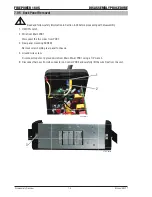
7.04 Front Panel (Operator Interface) Circuit Board PCB3 Removal
!
Read and follow safety information in Section 6.02 before proceeding with disassembly
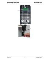
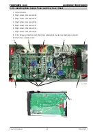
1. PROCESS Selector Switch Boot
Remove the rubber boot from the PROCESS Selector switch by turning the retaining nut counter clockwise.
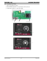
2. WELD CURRENT Control Knob
Remove the WELD CURRENT KNOB by loosening the set screw.
3. WELD CURRENT control mounting nut
Remove mounting nut.
4. Front Panel PCB3
Remove the Front Panel PCB3 from the panel.
5. Panel mounting screw
Remove screw.
A-12729
1
2
A-12730
3
Summary of Contents for TIG 160S
Page 6: ...This Page Intentionally Blank ...
Page 18: ...FIREPOWER 160 S INTRODUCTION Introduction 2 2 Manual 0 5371 Notes ...
Page 30: ...FIREPOWER 160 S SAFETY AND INSTALLATION Safety and Installation 3 12 Manual 0 5371 Notes ...
Page 40: ...FIREPOWER 160 S THEORY OF OPERATION Theory of Operation 5 2 Manual 0 5371 Notes ...
Page 54: ...FIREPOWER 160 S TROUBLESHOOTING Troubleshooting 6 14 Manual 0 5371 Notes ...
Page 59: ...DISASSEMBLY PROCEDURE FIREPOWER 160 S Manual 0 5371 7 5 Disassembly Procedure 4 Art A 09866 ...
Page 66: ...FIREPOWER 160 S DISASSEMBLY PROCEDURE Disassembly Procedur 7 12 Manual 0 5371 Notes ...
Page 69: ...ASSEMBLY PROCEDURES FIREPOWER 160 S Manual 0 5371 8 3 Assembly Procedures 8 Art A 09883 ...
Page 74: ...FIREPOWER 160 S ASSEMBLY PROCEDURES Assembly Procedures 8 8 Manual 0 5371 Notes ...
Page 78: ...FIREPOWER 160 S REPLACEMENT PARTS Replacement Parts 9 4 Manual 0 5371 Notes ...
Page 80: ...FIREPOWER 160 S ACCESSORIES Accessories 10 2 Manual 0 5371 Notes ...
Page 83: ......

