


FIREPOWER 160 S TROUBLESHOOTING
Troubleshooting
6-6
6-6
Manual 0-5371
!
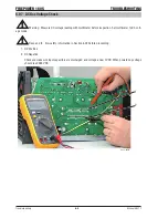
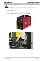
Read and follow safety information in Section 6.02 before proceeding.
Measure point 1 to 18.
1. Measurement of Input Rectifier
Set multimeter to diode mode. Diode voltage drop reading should be in the range of 0.200 V - 0.700 V.
Positive Probe
Negative Probe
Measure Point 2
Measure Point 1
Measure Point 4
Measure Point 1
Measure Point 3
Measure Point 2
Measure Point 3
Measure Point 4
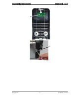
If reading is out of voltage drop range, disconnect two parallel rectifiers and measure separately to deter-
mine faulty rectifier and replace it.
2. Measurement of Main IGBT
Set multimeter to diode mode. Diode voltage drop reading shuld be in the range of 0.200-0.600V.
Positive Probe
Negative Probe
Measure Point 6
Measure Point 5
Measure Point 8
Measure Point 7
If reading is out of voltage drop range, replace main board.
3. Measurement of PFC IGBT
Set multimeter to diode mode. Diode voltage drop reading should be in the range of 0.200-0.600V.
Positive Probe
Negative Probe
Measure Point 9
Measure Point 10
If reading is out of voltage drop range, replace main board.
4. Measurement of Boost Diode
Set multimeter to diode mode. Diode voltage drop reading should be in the range of 0.200-0.600V.
Positive Probe
Negative Probe
Measure Point 12
Measure Point 11
If reading is out of voltage drop range, replace main board.
5. Measurement of Output Diode
Set multimeter to diode mode. Diode voltage drop reading should be in the range of 0.200-0.600V.
Positive Probe
Negative Probe
Measure Point 13
Measure Point 14
Measure Point 15
Measure Point 16
If reading is out of voltage drop range, replace main PCB1.
Summary of Contents for TIG 160S
Page 6: ...This Page Intentionally Blank ...
Page 18: ...FIREPOWER 160 S INTRODUCTION Introduction 2 2 Manual 0 5371 Notes ...
Page 30: ...FIREPOWER 160 S SAFETY AND INSTALLATION Safety and Installation 3 12 Manual 0 5371 Notes ...
Page 40: ...FIREPOWER 160 S THEORY OF OPERATION Theory of Operation 5 2 Manual 0 5371 Notes ...
Page 54: ...FIREPOWER 160 S TROUBLESHOOTING Troubleshooting 6 14 Manual 0 5371 Notes ...
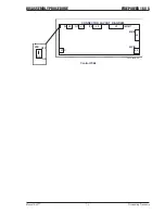
Page 59: ...DISASSEMBLY PROCEDURE FIREPOWER 160 S Manual 0 5371 7 5 Disassembly Procedure 4 Art A 09866 ...
Page 66: ...FIREPOWER 160 S DISASSEMBLY PROCEDURE Disassembly Procedur 7 12 Manual 0 5371 Notes ...
Page 69: ...ASSEMBLY PROCEDURES FIREPOWER 160 S Manual 0 5371 8 3 Assembly Procedures 8 Art A 09883 ...
Page 74: ...FIREPOWER 160 S ASSEMBLY PROCEDURES Assembly Procedures 8 8 Manual 0 5371 Notes ...
Page 78: ...FIREPOWER 160 S REPLACEMENT PARTS Replacement Parts 9 4 Manual 0 5371 Notes ...
Page 80: ...FIREPOWER 160 S ACCESSORIES Accessories 10 2 Manual 0 5371 Notes ...
Page 83: ......


