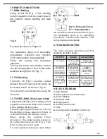
10
5.
Open the gas cylinder
valve (1). Press the torch button and check
that gas is flowing through correctly.
WARNING:
Cylinders contain high
pressure gas. Handle them with care.
Inappropriate treatment can cause serious
accidents. Do not pile gas cylinders up and
never expose them to excessive heat,
flames or sparks. Do not bang cylinders
against each other. Contact your supplier
for more information regarding the use and
maintenance of gas cylinders.
WARNING:
Never use cylinders that are
damaged or show signs of oil or grease
leakage. Contact your supplier immediately
of any such circumstances.
6. WELDING METHODS
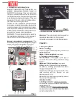
The welding mode is selected pressing
button 24 (Fig.1) repeatedly. Check the
correct mode has been selected, i.e. MMA
(LED21 on), normal TIG (LED22 on) or
pulsed TIG (LED23 on).
6.1 MMA Welding (LED 21, Fig 1 ‘on’)
Select this mode pressing button 24
repeatedly until LED21 lights up.
6.1.1 Description
Electric MMA (Metal Manual Arc) and
SMAW (Shielded Metal Arc Welding) are
both manual procedures exploiting the
heat generated by an electric arc that is
produced when covered welding
electrodes make contact with the
workpiece. It is commonly used due to
its versatility. In fact, welding jobs can
be performed anywhere: in a workshop,
in the open, in confined spaces or hard
to reach areas. A wide range of
electrodes are available, suiting all
requirements.
The arc is generated touching the electrode
to the workpiece.
The potentiometer knob (Fig. 1 –25)
regulates the welding current (thicker
workpieces require higher current settings).
6.1.2 MMA WELDING FEATURES
While welding the following features come
into effect:
Arc Force:
Whenever the arc tends to
drop the microprocessor automatically
increases the welding current in order to
maintain and stabilise the arc.
Hot Start:
The arc is generated touching
the electrode to the workpiece. To ensure
the arc is generated efficiently, the
microprocessor increases the welding
current for app. one second, , guaranteeing
fast, safe arc generation.
Antisticking:
Stops the welding current if
the operator makes a mistake causing the
electrode to stick to the workpiece. The
electrode can be removed from its clamp
without causing damaging sparks.
6.1.3 MMA WELDING
Proceed as follows for MMA welding:
1.
Using the button 33 (Fig. 1) set the right
polarity of the welding current. Usually
direct polarity (LED 30 ON).
Always check the suitable polarity indicated
in the electrode manufacurer’s instruction.
2.
According to the type of electrode and the
thickness of the workpiece, set the welding
current using Knob 25 (Fig.1). (The welding
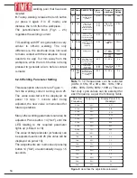
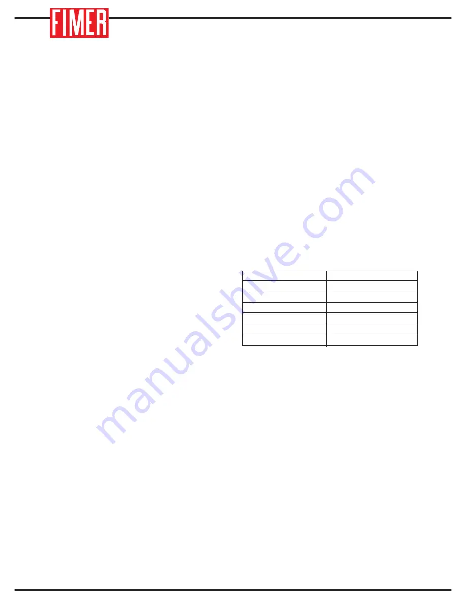
current value is shown on display 13). Figure
4 provides guidelines according to the
diameter of the specific electrode being used.
However, the electrode manufacturer’s
instructions should also be heeded.
DIAMETRO (mm)
CORRENTE (A)
35-50
40-70
60-100
80-140
120-170
180-250
1.6
2.0
2.5
3.25
4.0
5.0
Fig. 4
Electrode Diameter vs Welding
Current Considerations
Summary of Contents for TT165 AC/DC
Page 1: ...InstructionManual TT165 AC DC TT205 AC DC TT165 AC DC TT205 AC DC ...
Page 4: ......
Page 5: ...TT165 AC DC TT205 AC DC ...
Page 10: ...X ...
Page 12: ......
Page 30: ...20 NOTE ...
Page 32: ...Cod 910 100 333GB REV00 ...

