background image

5

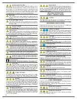
CLEAN ENVIRONMENT

Remove all flammable materials away from

the work environment.

SERIOUS DANGER ! 1

NEVER weld in confined spaces (e.g. in a con-

tainer vehicle, a cistern or a storeroom etc.) where toxic, inflamma-

ble or explosive materials are, or have been, located or stored.

Cisterns, in particular, may still contain toxic, flammable or explosi-

ve gases and vapours years after they have been emptied.

SERIOUS DANGER! 3

NEVER use the Welder to melt frozen water

pipes.

SERIOUS DANGER ! 2

NEVER weld a cistern that contains (or has stored)

toxic, inflammable or explosive materials.  They could

still contain toxic, flammable or explosive gases and vapours years

after they have been emptied. If you are obliged to weld a cistern,

ALWAYS passivate it by filling it with sand or a similar inert sub-

stance before starting any work.

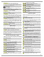
WELDING ENVIRONMENT VENTILATION

Ventilate the welding environment carefully. Maintain

sufficient air-flow to avoid toxic or explosive gas accumulation.

Welding processes on certain kinds or combinations of metals can

generate toxic fumes. In the event of this happening, use air-sup-

ply respirators.  BEFORE welding, read and understand the wel-

ding alloy safety provisions.

GAS TYPES

These welders use only inert (non-flammable) gases for welding

arc protection. It is important that the appropriate type of gas is

chosen for the type of welding being performed.

UNIDENTIFIED GAS CYLINDERS

NEVER use unidentified gas cylinders.

PRESSURE REGULATOR 1

NEVER connect the cylinder directly to the Welder.

Always use a pressure regulator.

PRESSURE REGULATOR 2

Check the regulator is performing its function properly.

Read the regulator instructions carefully. 

PRESSURE REGULATOR 3

Never lubricate any part of the regulator. 

PRESSURE REGULATOR 4

All regulators are designed for a specific type of gas.

Check the regulator is appropriate for the protective

gas to be used.

VENTILATION

VENTILATION

Together with the previous instructions, the following pre-
cautions should be strictly observed 

PROTECTIVE  WELDING  GASES

PROTECTIVE  WELDING  GASES

Together with the previous instructions, the following

precautions should be strictly observed when welding

with protective gases  

WALL AND FLOOR PROTECTION

The walls and flooring surrounding the welding

environment must be shielded using non-flammable materials. This

not only reduces the risk of fire but also avoids damage to the wal-

ls and floors during welding processes.

EXTINGUISHER

Place an approved and appropriately-sized fire extinguisher in

the work environment.

Check its working order regularly (carry out scheduled inspections)

and ensure that all parties involved know how to use one.

DAMAGED GAS CYLINDERS

NEVER use damaged or faulty cylinders.

CYLINDER RELOCATION

NEVER lift a gas cylinder by holding the regulator. 

GAS CYLINDERS

Do not expose gas cylinders to excessive heat sour-

ces, sparks, hot slag or flames.

GAS HOSE 1

Check the gas hose is not damaged.

GAS HOSE 2

Always keep the gas hose well away from the work

area.

ELECTRIC SHOCK

Together with the previous instructions, the following pre-
cautions should be strictly observed to reduce the risk of
electric shock 

ELECTRIC SHOCK INJURY

DO NOT touch a person suffering from electric shock if

he/she is still in contact with the cables. Switch the mains power
source off immediately THEN provide assistance.

CABLE CONTACT

Do not tamper with power cables if the mains power is still

switched on. Do not touch the welding circuitry. Welding cir-

cuitry is usually low voltage, however, as a precaution, do not tou-

ch the welder electrodes. 

CABLE AND PLUG PRECAUTIONS

Check the power supply cable, plug and wall-socket regularly.

This is particularly important if the equipment is relocated often.

REPAIRS

Never attempt to repair the Welder yourself. The result would
not only cause warranty cancellation but also high danger risks.

MAINTENANCE PRECAUTIONS

Always check that the electric power supply has been discon-

nected before performing any of the maintenance opera-

tions listed in this manual ( e.g. before replacing any of the fol-

lowing:  worn electrodes, welding wires, the wire feeder etc.) 

Never point the welding gun or the electrode towards yourself

or others.

Check no power supply cables, telephone cables or other

electrical items (e.g. computer cables, control lines etc.) are

in the vicinity of the Welder.

Check there are no telephones, televisions, computers or other

transmission devices close to the Welder.

ELECTROMAGNETIC COMPATIBILITY

Make sure that people with pace-makers are not in the imme-

diate vicinity of the Welder.
Do not use the Welder in hospitals or medical environments

(including veterinary surgeries). Make especially sure there

is no electrical medical equipment being used close to whe-

re welding is being done.

Should the Welder interfere with other apparatus, take the fol-

lowing precautionary measures:

1. 

Check the Welder’s side panels are securely fastened.

2.

Shorten the power supply cables.

Place EMC filters between the Welder and the power source. (Con-

tact Fimer Technical Dept. in this respect ) 

EMC compatibility : CISPR 11, Group 1, Class A.

Summary of Contents for TT165 AC/DC

Page 1: ...InstructionManual TT165 AC DC TT205 AC DC TT165 AC DC TT205 AC DC ...

Page 2: ...Istruzioni Originali Original instructions Übersetzung der Originalbetriebsanleitung Notice originale Manual original ...

Page 3: ...20050 RONCO BRIANTINO MI Italy Via Brigatti 59 Tel 39 039 6079326 Fax 39 039 6079334 www fimer com info fimer com ...

Page 4: ......

Page 5: ...TT165 AC DC TT205 AC DC ...

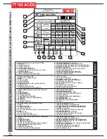
Page 6: ...OUDAGE 16 CYCLE INTERMITTENT 17 COURANT NOMINAL DE SOUDAGE 18 TENSION CONVENTIONNELLE DE CHARGE 19 ANNÉE DE PRODUCTION 1 NOMBRE DIRECCIÓN Y LOGOTIPO DEL FABRICANTE 2 MODELO 3 NÚMERO DE SERIE 4 ESQUEMA BLOQUES 5 SALIDA DE SOLDADURA 6 SE PUEDE UTILIZAR EN AMBIENTES CON MAYOR RIESGO DE DESCARGAS ELÉCTRICAS 7 ALIMENTACIÓN 8 GRADO DE PROTECCIÓN 9 TIPO DE CORRIENTE DE SOLDADURA 10 TENSIÓN NOMINAL EN VAC...

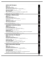
Page 7: ...pruebas de calentamiento se han realizado con una temperatura de 40 ºC FUNCIÓN FUERZA ARC Y ANTISTICKING DIÁMETROS DE LOS ELECTRODOS UTILIZABLES ITALIANO ENGLISH DEUTSCH FRANÇAIS ESPAÑOL ALTRI DATI TECNICI ALTRI DATI TECNICI ADDITIONAL TECHNICAL INFORMATION ADDITIONAL TECHNICAL INFORMATION WEITERE TECHNISCHE DATEN WEITERE TECHNISCHE DATEN CARACTERISTIQUES TECHNIQUES CARACTERISTIQUES TECHNIQUES OTR...

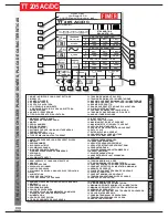
Page 8: ...ON DE SOUDAGE 16 CYCLE INTERMITTENT 17 COURANT NOMINAL DE SOUDAGE 18 TENSION CONVENTIONNELLE DE CHARGE 19 ANNÉE DE PRODUCTION 1 NOMBRE DIRECCIÓN Y LOGOTIPO DEL FABRICANTE 2 MODELO 3 NÚMERO DE SERIE 4 ESQUEMA BLOQUES 5 SALIDA DE SOLDADURA 6 SE PUEDE UTILIZAR EN AMBIENTES CON MAYOR RIESGO DE DESCARGAS ELÉCTRICAS 7 ALIMENTACIÓN 8 GRADO DE PROTECCIÓN 9 TIPO DE CORRIENTE DE SOLDADURA 10 TENSIÓN NOMINAL...

Page 9: ... INTERVENCIÓN Las pruebas de calentamiento se han realizado con una temperatura de 40 ºC FUNCIÓN FUERZA ARC Y ANTISTICKING DIÁMETROS DE LOS ELECTRODOS UTILIZABLES ITALIANO ENGLISH DEUTSCH FRANÇAIS ESPAÑOL ALTRI DATI TECNICI ALTRI DATI TECNICI ADDITIONAL TECHNICAL INFORMATION ADDITIONAL TECHNICAL INFORMATION WEITERE TECHNISCHE DATEN WEITERE TECHNISCHE DATEN CARACTERISTIQUES TECHNIQUES CARACTERISTIQ...

Page 10: ...X ...

Page 11: ...N pag 6 2 DESCRIPTION OF WELDER pag 6 3 CONNECTION TO POWER SUPPLY pag 8 4 OUTPUT CONNECTIONS pag 9 4 2 TIG WELDING CONNECTIONS pag 9 5 GASCYLINDERANDGASPRESSUREREGULATORCONNECTIONS pag 9 6 WELDING METHODS pag 10 6 1 MMA Welding pag 10 6 1 1 Description pag 10 6 1 2 MMA WELDING FEATURES pag 10 6 1 3 MMA WELDING pag 10 6 2 DC Welding pag 11 6 2 1 Description pag 11 6 2 2 Arc Generation Mode Lift or...

Page 12: ......

Page 13: ...e entire life of the equipment It should be kept within the operator s reach at all times Fires and explosions can seriously injure or cause dama ge Read understand and observe all safety warnings to reduce the risk of death or injury from fire or explo sion Pay particular attention to the fact that even bystanders should be aware of and understand the dangers existing in the welding area Remember...

Page 14: ...ver use damaged cables This applies to both the power and the welding cables DAMAGED CABLES Never remove the unit side panels If the side panels can be opened always checked they are closed tightly before starting any work HIGH VOLTAGE PROTECTION HIGH VOLTAGE PROTECTION Together with the previous instructions the following pre cautions should be strictly observed FIRE PREVENTION FIRE PREVENTION To...

Page 15: ...lace an approved and appropriately sized fire extinguisher in the work environment Check its working order regularly carry out scheduled inspections and ensure that all parties involved know how to use one DAMAGED GAS CYLINDERS NEVER use damaged or faulty cylinders CYLINDER RELOCATION NEVER lift a gas cylinder by holding the regulator GAS CYLINDERS Do not expose gas cylinders to excessive heat sou...

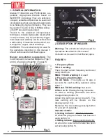
Page 16: ...age 6 2 DESCRIPTION OF WELDER Warning The unit should only be used for operations described in this manual It should not be used to melt frozan pipes FIGURE 1 1 Frequency Knob TIG AC welding The AC output current frequency can be set using this Knob MMA TIG DC welding Not used 2 Frequency Confirmation TIG AC Mode This lights up for app 4 seconds for each setting selected using Knob 1 MMA and TIG D...

Page 17: ...g of TIG welding button 14 shows the value of the parameter The following information will also be displayed When unit is switched on welder model and firmware version Should the letters E Ln appear on the display and the LED 11 lights up it means the power supply is below the standard required 14 Welding Parameter Selector The parameter to be adjusted can be selected The button is used together w...

Page 18: ...G welding A start or stop command is relayed from the torch to the unit If a welding pedal optional accessory is used a suitable current level command is also sent In the latter case the torch button is automatically disabled 37 Gas Hose Connector MMA welding Not used TIG welding Torch hose connection 38 Earth Clamp MMA welding Earth Clamp TIG welding Earth Clamp FIGURE 2 39 Fuse 40 ON OFF SWITCH ...

Page 19: ... the groove insert the plug and screw it in well clockwise Do not over tighten 2 Connect the torch to the appropriate socket Fig 1 35 Lining up the peg and the groove insert the plug and screw it in well clockwise Do not over tighten Connect the torch remote signal connector to socket 36 Fig 1 on the front panel of the unit Do not over tighten 5 GAS CYLINDER AND GAS PRESSURE REGULATOR CONNECTIONS ...

Page 20: ...he arc is generated touching the electrode to the workpiece The potentiometer knob Fig 1 25 regulates the welding current thicker workpieces require higher current settings 6 1 2 MMA WELDING FEATURES While welding the following features come into effect Arc Force Whenever the arc tends to drop the microprocessor automatically increases the welding current in order to maintain and stabilise the arc...

Page 21: ...ul when accurate welding is required on a wide range of thicknesses when welding in awkward positions or where deep fillings are required on pipes for instance In TIG mode a variety of materialscanbewelded ferrousmaterials nickel alloys copper titanium magnesium etc It is not however advisable for aluminium Before welding the following settings must be programmed 1 Arc generation mode Lift or HF 2...

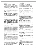
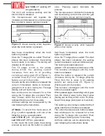
Page 22: ...ss as soon as the button is pressed once Pressing again terminate the process The microprocessor controls the increasing and decreasing current time and the gas flow in order to ensure optimum results Gas flows immediately when the torch button is pressed Once the T1 stage the so called Pre Gas phase has been completed the welding current increases to a pre set initial level ls The factory set par...

Page 23: ...ing process Pulsed Welding In this case the welding current will not remain constant at the l2 value set using knob 25 Fig 1 It will continue to alternate between the l2 value and a much lower ls value so called background current The alternation frequency between the two values is adjustable the factory set frequency is 30Hz but that can be adjusted following the instructions below The length of ...

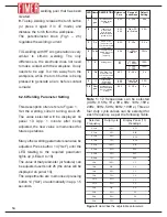
Page 24: ... 1 5 seconds Note 1 12 frequencies can be selected 0 3Hz 0 5Hz 1Hz 3Hz 5Hz 10Hz 15Hz 20Hz 30Hz 50Hz 80Hz 100Hz Three or four duty cycle values can be selected for each frequency as per the following Table LED Name Pre gas Is Su Pulse I2 Sd If Post gas Pre Gas Phase Gas flow before welding Initial Current Current when torch button is pressed and back ground current Slop UP Time Time between ls curr...

Page 25: ... Arc generation mode Lift or HF 2 Welding mode 2T 4T or 4T Bi Level 3 Welding procedure Normal or Pulsed 6 3 2 Arc Generation Mode Lift or HF The arc can be generated either by touching the electrode to the workpiece Lift mode or by approaching the torch to torch to the workpiece HF mode Lift generation minimises electromagnetic disturbance and weld pool pollution To select Lift mode press button ...

Page 26: ...mmediately when the torch button is pressed Once the T1 stage the so called Pre Gas phase has been completed the welding current increases to a pre set initial level ls The factory set parameters are duration 0 5 seconds ls current value 20A This remains unchanged until the torch button is released When the button is released the current increases during the T2 stage Slop Up Time from the ls value...

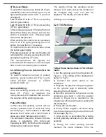
Page 27: ...requency is 30Hz but that can be adjusted following the instructions The length of time the welding current remains al l2 value versus the duration of the complete duty cycle can also be adjusted The factory set ratio is 50 Welding can now begin 6 3 5 TIG Welding Follow these instructions in TIG Lift Arc mode 1 Set the welding current turning knob 25 Figure 1 The setting will be displayed on panel...

Page 28: ...Table LED Nome Pre gas Is Su Pulse I2 Sd If Post gas Tempo di Pre Gas Tempo in cui viene fatto fluire il gas prima di iniziare la saldatura Corrente iniziale corrente al momento della pressione del pulsante torcia e corrente di back ground Slop UP Time tempo in cui la corrente passa dal valore Is al valore I2 Frequenza e duty cycle di pulsazione frequenza di ripetizione della pulsazione Corrente d...

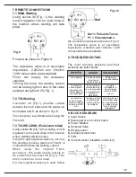
Page 29: ...edal needs merely to be connected to socket 36 Fig 1 The torch connector is not used If a non original accessory is used follow the connection instructions shown in Fig 10 The resistance value is of secondary importance 2 2kOhm and 10kOhm 1 2W components are acceptable 8 TROUBLESHOOTING The most common problems and their solutions are listed below 9 BLOCK DIAGRAM 1 Input Switch 2 Mains power and c...

Page 30: ...20 NOTE ...

Page 31: ...EG über Elektro und Elektronik Altgeräte und Umset zung in nationales Recht müssen verbrauchte Elektrowerkzeuge getrennt gesammelt und einer umweltgerechten Wiederverwertung zugeführt werden No tirar nuncalos aparatos eléctricos junto con los residuos en general De conformidad a la Directiva Europea 2002 96 EC relativa a los Residuos de Equipos Eléc tricos o Electrònicos RAEE y al acuerdo de la le...

Page 32: ...Cod 910 100 333GB REV00 ...

Reviews: