background image


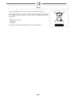
DISPOSAL 


To dispose of the appliance, take it to a demolition centre or an authorised collection centre. 


Before scrapping the machine it is necessary to remove and separate the following materials and send 

them to the appropriate collection centres in accordance with the environmental hygiene regulations 

currently in force: 


Felt 


Electric and electronic parts* 


Plastic parts 


Metallic parts 


(*) In particular, to scrap the electric and electronic parts, contact your area distributor. 


Page 26 


Summary of Contents for FV10 ECO ENERGY

Page 1: ...USE AND MAINTENANCE MANUAL FV10 ECO ENERGY FV15 ECO ENERGY ED 06 2014 EN ORIGINAL INSTRUCTIONS Doc 10045505 AA Version ...

Page 2: ...of the operator and the appliance Disposal symbol Carefully read the sections marked with this symbol for the disposal of the machine QUICK REFERENCE ELECTRONIC DOCUMENT For quick reference of the electronic documents use the Bookmarks and Links Pages Bookmarks Activate the Bookmarks panel of the interface browser clicking the related icon 01 the icon may vary depending on the version of the Acrob...

Page 3: ...TION BAG 9 PREPARING TO WORK 11 WORK 13 1 NOISE LEVEL AND ENERGY CONSUMPTION REDUCTION VERSION FV15 13 AT THE END OF THE WORK 14 DAILY MAINTENANCE 15 1 EMPTYING THE COLLECTION TANK 15 2 CLEANING ACCESSORIES 16 WEEKLY MAINTENANCE 17 1 CLEANING THE COLLECTION TANK 17 2 CLEANING THE FABRIC FILTER 17 3 CLEANING THE VACUUM MOTOR FILTER 18 4 CLEANING THE EXHAUST AIR FILTER 19 EXTRAORDINARY MAINTENANCE 2...

Page 4: ...n or under jets of water IT IS FORBIDDEN to use the appliance for picking up dangerous dusts or inflammable liquids in places with an explosive atmosphere In addition it is not suitable as a means of transport for people or objects This appliance should only use for the purpose for which it was constructed namely cleaning inert surfaces the aspiration of solid non flammable and non explosive subst...

Page 5: ...e main switch Air flow rate regulation lever symbol Used in the vacuum head to indicate the lever for regulating the air flow rate during the vacuum phase OPEN symbol Used in the vacuum head to indicate the lever that allows you to remove the vacuum head from the collection tank Page 4 ...

Page 6: ...cleaner with the power cable twisted around the lid Before connecting the appliance to the electrical socket make sure that the electrical information reported on the plate corresponds to that of the mains supply The appliance must only be powered with a voltage equal to that shown on the serial number plate When the accessory is operating do not bring it close to delicate organs like ears mouth e...

Page 7: ...Open the outer carton 2 Remove the accessories inside the carton and gently lay them on the ground WARNING You are advised to always wear protective gloves to avoid the risk of serious injury to your hands 3 Take out the vacuum head carton 4 Take out the appliance from the box using the handle 1 taking care not to damage either 5 Take out the appliance from the protective bag using the relative ha...

Page 8: ...r preventing damage during transportation 5 Insert the accessories support and the head block inside the carton 6 Place the accessories in the carton 7 Close the carton 4 COMPONENTS OF THE APPLIANCE The basic components of the appliance are as follows 1 Collection tank unit 2 Fabric filter 3 Vacuum head unit 4 Power cable 5 COLLECTION TANK COMPONENTS The components of the collection tank are as fo...

Page 9: ...ter locking mesh 9 Exhaust air filter 10 Power cable winding bracket only for FV15 11 Vacuum head coupling lever 12 Fabric bag filter 13 Sponge filter locking mesh 14 Vacuum motor filter 7 APPLIANCE SAFETY The stages for making the appliance safe and thereby allowing all the operations to be carried out in complete safety are as follows 1 Make sure that the collection tank is empty and if not empt...

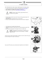
Page 10: ...RTING FILTER PAPER COLLECTION BAG To insert the filter collection bag inside the collection tank proceed as follows 1 Make sure the machine is in a safe condition read MACHINE SAFETY WARNING you are advised to always wear protective gloves to avoid the risk of serious injury to your hands 2 Remove the vacuum hose 1 turning it anti clockwise and remove it from the vacuum nozzle 2 in the collection ...

Page 11: ...be used for collecting solid waste 7 Using the handle 4 on the vacuum head assembly position the vacuum head assembly on the collection tank Being very careful to insert the coupling levers 7 in the vacuum head inside the interlocking couplings 8 in the collection tank 8 Secure the vacuum head to the collection tank using the lever 3 on the front part of the collection tank moving the lever as ind...

Page 12: ...um hose to the collection tank rotate in a clockwise direction 4 Select the most suitable accessory for the task at hand see the chapter CHOOSING AND USING THE ACCESSORY WARNING Never use the appliance without the correct filter for the type of work to be carried out see the section REPLACING THE VACUUM MOTOR FILTER or else REPLACING THE EXHAUST AIR FILTER 5 Insert the extension inside the nozzle ...

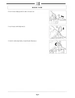
Page 13: ...RING TO WORK 10 Insert the power cable plug 6 into the socket on the vacuum cap 11 Insert the power cable locking bracket 5 12 Secure the cable locking bracket by turning the bracket locking lever 4 Page 12 ...

Page 14: ...section NOISE LEVEL AND ENERGY CONSUMPTION REDUCTION VERSION FV15 If while working you see that the vacuum accessory is sticking to the surface too much proceed as follows 1 Shift the lever in the grip of the vacuum hose in the direction of the arrow 2 Proceed with the vacuuming and free the accessory 1 NOISE LEVEL AND ENERGY CONSUMPTION REDUCTION VERSION FV15 If while working you want to reduce t...

Page 15: ...der a jet of running water 6 Remove the extension inside the nozzle in the vacuum hose clean it under a jet of running water 7 Take the appliance to the designated machine storage place 8 Wind the power cable around the cable winder 2 on the bottom of the handle only valid for FV15 versions 9 Insert the vacuum hose fixing clip 3 into the support at the rear of the collection tank WARNING Park the ...

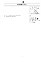
Page 16: ... vacuum head from the collection tank using the lever 3 on the front rear part of the collection tank moving the lever as indicated by the arrow in the picture on the side 5 Using the handle 4 in the vacuum head assembly remove the vacuum head assembly from the collection tank rotating it and shifting it as indicated in the figure 6 Lay the head gently on the floor 7 Remove the dirt from the colle...

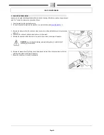
Page 17: ...om the extension clean it under a jet of tap water and place it in the accessory holder 1 4 Disconnect the extension end and clean it under a jet of tap water 5 Remove the extension inside the nozzle in the vacuum hose clean it under a jet of tap water WARNING you are advised to always wear protective gloves to avoid the risk of serious injury to your hands 6 Remove the vacuum hose 2 turning it an...

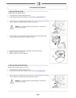
Page 18: ...he handle 4 in the vacuum head assembly remove the vacuum head assembly from the collection tank rotating it and shifting it as indicated in the figure 6 Lay the head gently on the floor 7 Rinse the inside of the collection tank with a jet of tap water 8 Dry the inside with a cloth 9 When dried repeat the operations in reverse to reassemble 2 CLEANING THE FABRIC FILTER Carefully cleaning the fabri...

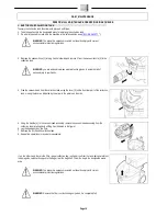
Page 19: ...um motor filter prolongs the life of the appliance Proceed as follows to clean the vacuum motor filter 1 Take the appliance to its designated maintenance area 2 Do what is required to make sure the machine is in a safe condition see MACHINE SAFETY 3 Free the vacuum head from the collection tank using the lever 1 on the front rear part of the collection tank moving the lever as indicated by the arr...

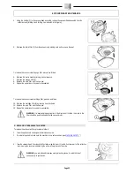
Page 20: ...E VACUUM MOTOR FILTER WARNING It is advisable to pay attention to the direction of filtration the mesh in the filter should be opposite the vacuum motor 4 CLEANING THE EXHAUST AIR FILTER Carefully cleaning the exhaust air filter of the vacuum motor prolongs the life of the appliance To clean the exhaust air filter proceed as follows 1 Take the appliance to its designated maintenance area 2 Do what...

Page 21: ...AIR FILTER To remove the vacuum motor cartridge filter proceed as follows 9 Remove the mesh 4 and the exhaust air filter 5 10 Clean the cartridge filter with an air jet from a distance of at least 20 cm 11 Repeat the operations in reverse to reassemble WARNING Check the state of wear of the vacuum motor filter if the filter surface area is blocked or has been damaged replace according to the secti...

Page 22: ...um head assembly from the collection tank rotating it and shifting it as indicated in the figure 5 Remove the fabric filter 3 from the vacuum cap making sure not to remove the seal 6 Replace the worn filter with the new one 7 Repeat the operations in reverse to reassemble 2 REPLACING THE VACUUM MOTOR FILTER Proceed as follows to replace the vacuum motor filter 1 Take the appliance to its designate...

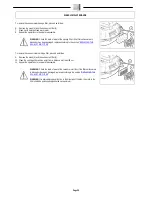
Page 23: ...r 6 by rotating it anticlockwise 11 Replace the worn filter with the new one 13 Repeat the operations in reverse to reassemble WARNING It is advisable to pay attention to the direction of filtration the mesh in the filter should be positioned opposite the vacuum motor 3 REPLACING THE EXHAUST AIR FILTER To replace the exhaust air filter proceed as follows 1 Take the appliance to its designated main...

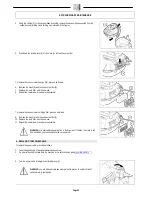
Page 24: ...filter proceed as follows 9 Remove the mesh 4 and the exhaust air filter 5 10 Replace the worn filter with the new one 12 Repeat the operations in reverse to reassemble WARNING It is advisable to pay attention to the direction of filtration the mesh in the filter should be positioned opposite the vacuum motor 4 REPLACING THE POWER CABLE To replace the power cable proceed as follows 1 Take the appl...

Page 25: ...EXTRAORDINARY MAINTENANCE 4 Remove the power cable locking bracket 2 5 Remove the damaged power cable 3 and replace it with a new cable 6 Repeat the operations in reverse to reassemble Page 24 ...

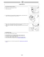
Page 26: ...re that the power cable has not been damaged read the section REPLACING THE POWER CABLE 2 INSUFFICIENT VACUUM If the vacuum capacity is insufficient proceed as follows 1 Check that the vacuum hose is connected properly to the nozzle on the collection tank 2 Check that the vacuum hose is connected properly to the accessory that is being used 3 Check that there is nothing obstructing the vacuum hose...

Page 27: ...cessary to remove and separate the following materials and send them to the appropriate collection centres in accordance with the environmental hygiene regulations currently in force Felt Electric and electronic parts Plastic parts Metallic parts In particular to scrap the electric and electronic parts contact your area distributor Page 26 ...

Page 28: ... input current 16 A per phase EN 61000 3 3 Electromagnetic compatibility EMC Part 3 3 Limits Restriction of voltage variations voltage fluctuations and flicker in low voltage power supply systems for devices with a rated current 16 per phase and not subject to conditional connection EN 55014 1 Electromagnetic compatibility Regulations for household appliances electrical devices and similar equipme...

Reviews: