


Chapter 3 – Configuration
Setting the hardware modes
Truelight SDI User Guide
13
Setting the hardware modes
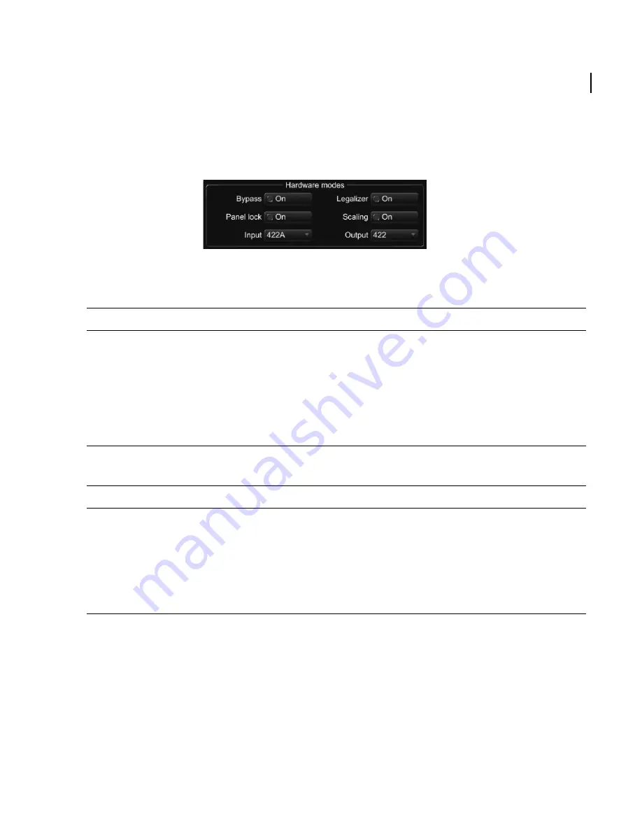
The Hardware modes section on the Hardware panel sets up the input and output video
modes and provides control over other functions of the unit.
Select the
Input
list to set the input mode:
Select the
Output
list to set the output mode:
Note that these settings apply globally to all cubes. Therefore, to correctly configure the
unit it is necessary to know the creation mode of the cube (RGB/YCrCb) and whether it was
generated with scaling enabled or disabled. If you have cubes installed that were created
in different modes then it is recommended to include an appropriate reference (for
example ‘RGB-Scaled’ or ‘YCrCb-Unscaled’) as part of the file name for the profile used to
generate the cube.
Figure 3-3:
Hardware modes
Mode
Description
422A
The input mode is set to 4:2:2 (YCrCb) and the signal is taken from the IN A connector.
422B
The input mode is set to 4:2:2 (YCrCb) and the signal is taken from the IN B connector.
444 YUV
The input mode is set to 4:4:4 YCrCb (this requires a dual-link input to both IN A and IN B
connectors).
444 RGB
The input mode is set to 4:4:4 RGB (this requires a dual-link input to both IN A and IN B
connectors).
Mode
Description
422
The output mode is set to 4:2:2 (YCrCb) and the same signal is available on both the OUT
A and OUT B connectors.
444 YUV
The output mode is set to 4:4:4 YCrCb (this feeds a dual-link output via the OUT A and
OUT B connectors).
444 RGB
The output mode is set to 4:4:4 RGB (this feeds a dual-link output via the OUT A and OUT
B connectors).


