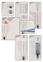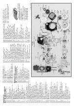
Ball bearing
7x11x3
Alloy dam-
per rever-
sing
Alloy
reversing
plate
Screw
4x12
Screw
5x25
Nut M4
Headless
pin 4x20
Disk
Ø 4,3
Push rod
mounted
ca
.3
0,5
m
m
Collet
Headless
pin 3x3
Nut M4
Headless
pin
5x5
Screw
4x25
Bearing
bush
Disk Ø 5,3
Screw
5x25
ca. 45mm
Ball bearing
7x11x3
Alloy dam-
per rever-
sing
Screw
4x14
Screw
2,9x13
Screw
4x25
Distance
disk
Screw
3x20
Nut
M4
Disk
Ø 4,3
Headless
pin
4x20
Front axle
carrier right
Fro
nt a
xle
carrie
r le
ft
Steel
ball
6mm
Ball
joint
6mm
Rods
4x43
Ball
joint
7mm
Ball
collet
7mm
Headless
pin
M4x4
Stabilizer 3mm
Stabilizer
shaft
Headless
pin
M4x4
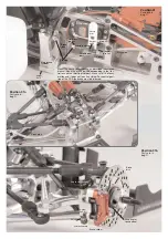
Position 19
Parts are
bags E+J
Position 19a
Parts are in
bags E+J
Position 18
Parts are in
bags E+J
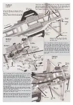
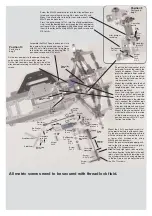
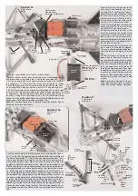
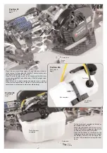
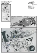
Mount 2,9x13 pan-head screws into the
plastic ball-and-socket joints of the push
rod. Fix the pre-asssembled push rod
at the bottom to the front lower alloy
wishbones using M4x25 pan-head
screws. Fix the pre-assembled push rod
at the top to the alloy damper reversings
using M4x14 cylinder screws.
Hint:
Pay attentin to the balls in the ball-
and-socket joints, mount the ball with
lowering with the cylinder screw. The
clearance of the balls can be adjusted
with the 2,9x13 screws in the ball joints.
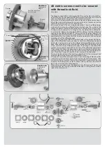
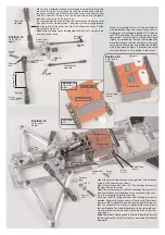
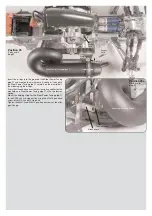
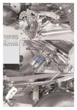
Screw M4x20 headless pins centrally in the alloy baffle and se-
cure it with disks Ø4.3 and M4 nuts. Mount the alloy baffle to
the front axle carrier by using M4x12 pan-head screws .
Mould the ball bearings 7x11x3 into the alloy reversing plate,
insert the bearing bushes through the alloy reversing plates
which are equipped with ball bearings and mount it to the al-
loy baffle using M5x25 pan-head screws and disks Ø5.3.
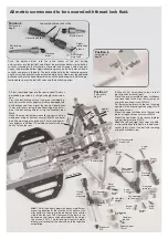
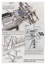
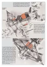
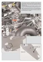
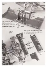
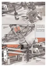
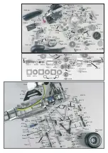
Screw the ball-and-socket joints 6mm and 7mm
on the rods to the length of approx. 30,5mm, then
push the steel balls 6mm and ball collets 7mm in
the same direction into the ball-and-socket joints
6mm and 7mm. Mount the stabilizer flush into
ball collets 7mm using a headless pin M4x4.
Press the stabilizer shaft with distance disks bet-
ween the front axle carriers, insert both stabilizer
rods 3mm in the stabilizer shaft, align the stabi-
lizer rods between the front axle carriers using
the distance disks and mount them with M4x4
headless pins. It may be necessary to grind the
distance disks slightly with an emery cloth. Mount
the ball-and-socket joint with steel balls 6mm,
M3x20 pan-head screws and damper mount of
the shock absorber through the outer hole to the
alloy damper reversing plates. Press M4x25 pan-
head screws into the front axle carriers and se-
cure with M4 nuts and M5x5 headless pins. Press
the shock absorbers onto the protruding threads,
then secure them with collets and M3x3 head-
less pins.
Hint:
The stabilizer rods should be mounted pa-
rallel to the shock absorber.


