
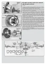
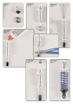
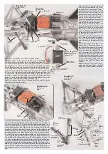
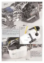

Push the distance disks into the round recess of the ball driving
axle as well as into the ball diff. axle. Mount the protection bellows to the ball dri-
veshafts according to the illustration. Lubricate the ball range a little when put-
ting on the protection bellow. Apply lubrication grease on the ball holes of the dri-
veshafts and press in the balls. The balls will be held by the lubrication grease
and this way the driveshaft can be mounted more easily. Now press the complete
ball driveshaft into the ball differential axle and the ball driving axle. Shift the pro-
tection bellows over the ball diff. axles and the ball driving axles.
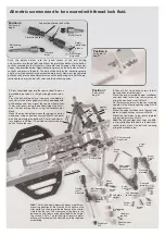
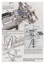
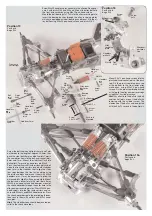
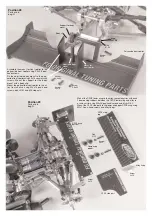
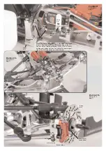
Position 7
Parts are in
bag B
Driving
shaft
mounted
Left alloy
upright
Headless
pin 6x6
Wheel nut
M6
Square wheel
14 mm
Screw
4x12
Distance
bush
Ball bearing
8x22x7
Ball bearing
8x22x7
Pay attention
to the slant
Screw
5x16
Screw
5x16
Screw
5x20
Rear axle
plate left
Screw
5x20
Bevel
washer
Driving dir
ection
Track rod
mounted
Screw
2,9x13
Screw
2,9x13
Rear upper
wishbone
left mounted
Screw
4x35
Screw
4x35
Ball diff. axle
Alloy rear axle
mount left
approx.
21,5mm
appr
ox.
39mm
approx.
10,5mm
Hint:
The left and right upper wishbones are different,
mounting direction of the steel ball with collar on the
alloy upright is showing to the bottom and the shorter
side faces the rear. The clearance of the balls in the
ball-and-socket joints can be adjusted with the help of
the screws 2.9x13. The left and right rear axle plates
differ, pay attention that the slant shows to the top when
assembling.
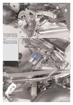
Apply
lubrication
grease.
Lubricate ball driveshaft a little.
Protection bellow
Ball diff. axle
Ball driving
axle
Distance
disks
Balls for dri-
ving shaft
Position 5
Parts are in
bag B
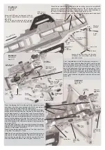
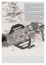
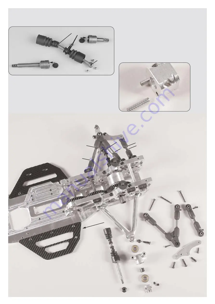
1.
Press the cylinder pins into the square wheel 14mm as
described in position 6, use high-strength screw reten-
tion.
Press the ball driving axles of the pre-assembled dri-
veshafts into the alloy uprights which are equipped with
ball bearings and then mount the square wheel driver
14mm with recess facing the ball bearing on the flat si-
de of the ball driving axle by using the headless pins
M6x6.
Mount the alloy upright between alloy upright and alloy
wishbones using a countersunk screw M5x20 and bevel
disk (thin side facing the ball bush). The left and right al-
loy uprights are different. The milled surface for the bra-
ke has to face the rear.
2.
Mount 2,9x13 pan-head screws into all
plastic ball-and-socket joints.
Mount the pre-assembled upper wishbones
and track rods to the alloy rear axle mounts
using the pan-head screws M4x35.
Fix the rear axle plates with the slant showing
upwards to the alloy uprights by using M5x16
pan-head screws.
Mount the upper wishbones to the rear axle
plates using countersunk screws M5x20.
Mount the track rods to the rear axle plates
using cylinder screws M4x12.
Hint
: The left and right track rods are diffe-
rent, pay attention to the balls in the ball-and-
socket joints, mount the ball with lowering
using the cylinder screw.
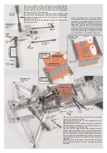
All metric screws need to be secured with thread lock fluid.
Position 6
Parts are in
bag B


