Servohebel
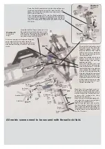
Screw
3x18
Screw
4x20
Screw
2,9x13
Ball joint
Ball joint
6mm
Alloy joint
ball
Track rod
mounted
Steering rods
mounted
Stop nut
M4
Stop nut
M3
Steel ball
6mm
Servo saver
mounted
Position 13
Parts are in
bag H
appr
ox. 45mm
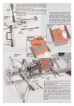
Front axle
carrier right
Screw
3x18
Screw
4,2x16
Screw
5x25
Distance
disk
Distance
bolt
Stop nut
M3
Steering servo
Steering servo
Servo fixing
brace
Steering rod
s
mounted
Disk Ø
5,3
Screw
4,2x19
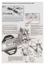
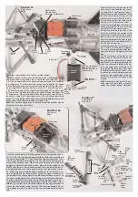
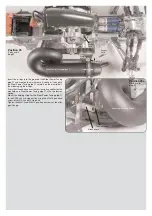
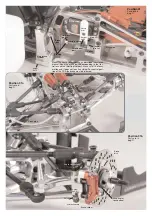
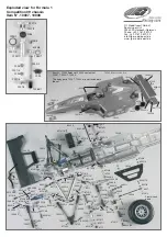
Mount the assembled steering rods through the steel balls 6mm with
the collar facing the servo saver into the outer thread holes of the al-
loy servo saver by usin g M3x18 pan-head screws and secure them
with M3 stop nuts. Screw 2,9x13 pan-head screws into the plastic
ball-and-scket joints of the track rods.
Fix the mounted track rod into the front outer hole of the servo saver
by using M4x20 cylinder screws. The cylinder screw must go through
the alloy joint ball, the collar must face the alloy servo saver. Fasten
it all with M4 stop nuts.
Hint:
The ball clearance can be adjusted with the 2,9x13 screws in the
ball-and-socket joints.
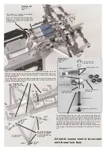
Steering servo
Steering servo
Servo fixing
brace
Position 14
Parts are in
bag H
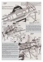
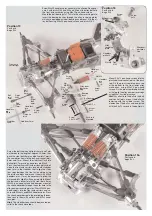
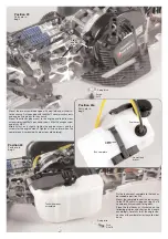
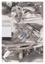
Mount the steering servos with the enclosed fi-
xing rubber bushings and screws to the servo fi-
xing braces as described in position 14. Switch on
your RCS and bring the steering servos in neu-
tral position. The servo arms have to be shortened
slightly corresponding the type. For competition
we recommend to use alloy servo arms. Press the
servo arms on the servos as pictured and fix them
with the enclosed screws. Preferably the servo
arms should be in a 90° position to the servo.
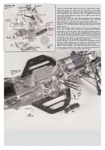
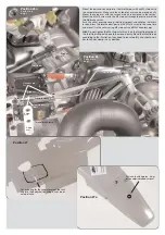
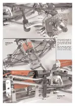
Mount the servo fixing braces on the right front axle carrier by
using 4,2x16 countersunk screws.
Mount the distance bolt with a 4,2x19 countersunk screw to
the right front axle carrier.
Mount the servo saver with a M5x25 countersunk screw, Ø 5,3
disk and distance disk between servo saver and alloy chas-
sis in the rear hole of the alloy chassis.
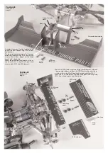
Switch on the RCS, bring the trim of the steering into central
position. Align servo saver in centre of the chassis. First mount
one servo rod using M3x18 pan-head screw and M3 stop nut,
then the second in the same way. Adjust both servo rods in
the same length. You should be able to fix the servo rods ea-
sily and without any resistance on the servo arms of the stee-
ring servos.
Hint:
Adjust both steering rods in the same length by turning
the ball-and-socket joints. Servo saver and servo arm should
be parallel.
Servo arm
Steering servo
Servo fixing
brace
Position 14
Parts are in
bag H
Position 15
Parts are in
bag H


