


3
turns off the mail box (by selecting 0 mailbox slots), the DVR test feature is also disabled. If the
mail box is turned off, the seven prompt tracks can be used as general system tracks. On power
up, the DVR clears all tracks (but not configuration data like prefixes, record time allocations,
etc..., these are maintained in nonvolitile memory). Thus, the mail box prompt tracks must be
recorded after power up in order for the mail box prompts to function properly. A battery back-up
connector is provided to maintain the DVR speech memory in the event of a power failure. The
installation section discusses the connection of an appropriate battery.
Installation
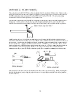
The wiring of the DVR is accomplished through three connectors on the FF-8070 board. The
following lists those connectors along with their signal descriptions:
~ = Active low signal
P2: Battery
* P3a: DVR I/O
* P3 (legacy)
P5: SPI Bus
* P3: DVR I/O
(molex 3 pin)
(IDC 10 pin)
(molex 9 pin )
(IDC 10 pin)
(2 pin header)
1) Battery (-)
1) DVR in (A)
1) DVR in (A)
1) MOSI
2) Battery (+)
2) GND
2) GND
2) GND
2) GND
3) Battery (-)
3) DVR out
3) ~CMD unlock
3) SPCK
3) ~CMD unlock
4) GND
4) n/c
4) GND
5) GND
5) n/c
5) MISO
6) GND
6) DVR in (B)
6) GND
7) DVR in (B)
7) DVR out
7) ~RST1
8) +12V in
8) +12V in
8) n/c
9) GND
9) GND
9) n/c
10) +12V in
10) Reset
* Note: legacy P3 connector supports FF-800 controllers manufactured prior to 2001 and is
generally not installed.
P1 & P4 are for DVR expansion and their pin-outs are detailed in the schematic for user reference.
The battery input (P2) should be connected to a battery for maintaining DVR operation during
power interruptions. The battery must be greater than 9 volts accross its discharge cycle, and less
than the voltage at P3-8 for proper operation. A 3 AHr lead-acid-cell will maintain power for over
30 hours. It is generally recommended that a 12V battery be used with at least 1Ahr of capacity.
Note that the FF-8070 has no provisions for charging the back-up battery, an external
charge/maintenance system must be supplied by the user.
P3a and P5 use factory supplied ribbon cables to connect to the FF-800. P3a on the DVR connects
to P25 on the FF-800, while P5 on the DVR connects to P7 on the FF-800.
The FF-8070 card should be placed in an RF tight enclosure and be placed as close as practical to
the FF-800. It is recommended that the FF-8070 be installed in the same chassis as the FF-800 to
allow the cable lengths to be kept to a minimum.
DVR Functions
The FF-800 SPI interface commands use a prefix-suffix syntax. The user-defined prefixes may be
1 to 4 digits long and are used to access the various interfaces connected to the FF-800 SPI bus.
The SPI protocol assigns a fixed address to each interface that is connected to the bus. These
addresses are factory defined and are used to differentiate the devices (the FF-800 does not have
any specific programming that differentiates one address from another). The DVR address is 6, so
the FF-800 commands for accessing the DVR are the SPI #6 Command (default 130) or the
generic SPI Command plus the address "6" (default 1266). One of these prefixes must precede
Summary of Contents for FF-8070
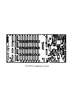
Page 19: ...FF 8070 Component Layout...


