background image

14

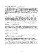
APPENDIX A: FF-8070 WIRING

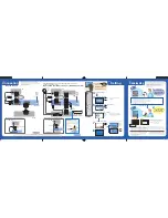
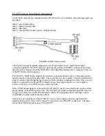
The connections to the FF-8070 are all accomplished via 10 conductor ribbon cable.  There are two
cables provided, one for the power/audio (connects P3 on the DVR to P25 on the FF-800) and one
for SPI communications (connects P5 on the DVR to P7 on the FF-800).  The only remaining
connection is that of a back-up battery to P2 of the DVR.

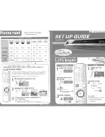
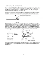
For external connections, use shielded or twisted pair cable along with the provided housings and
crimp pins.  Cut the cable to the shortest possible length and strip back the outer sheath 1 inch.
Unravel the braid and twist together as shown below and remove the foil inner shield (if present).

1"

Solder hook-up wire here

Solder a short piece (1 or 2 inches) of hookup wire to the shield as shown above and cut off the
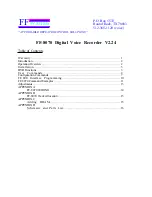
remainder of the shield.  Cut this wire even with the others and trim 0.1" of insulation from the end
of each wire.  Using a pair of needle-nose pliers, crimp the exposed conductor into a molex pin as
shown at (1) below.  Apply a small amount of solder to establish a good connection.  If too much
solder is applied, it could wick down to the end of the pin at (4) -- this will make the pin difficult to
insert and it may not retain properly.  If this occurs, the pin should be discarded and another
installed in its place.  After all pins are secured, crimp at (2) around the insulation for strain relief.

Molex housing

Molex pin detail

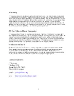
The shield wire should connect to the GND connection of the specific housing.  When inserting the
pin into the housing, be sure that the contact loop at (3) is oriented toward the tabs on the housing
as shown above.

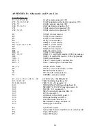
Summary of Contents for FF-8070

Page 1: ...FF 8070 Operations Manual Digital Voice Recorder Revised December 14 2002 Copyright FF Systems 2001 2002 All Rights Reserved...

Page 2: ...e of Contents Warranty 1 Introduction 2 Operation Overview 2 Installation 3 DVR Functions 3 User Commands 4 Configuration Commands 7 FF 800 Interface Programming 10 FF 8070 Command Examples 11 Adjustm...

Page 3: ...ays after shipment from FF Systems If the purchaser decides to return a product they must contact FF Systems for a Return Material Authorization RMA number on or before 6 00pm central time within 35 c...

Page 4: ...stream is stored on 1 megabit DRAMS each of which can hold about 20 seconds of sampled audio The FF 8070 comes standard with 8 one megabit DRAMS with room for additional memory up to a maximum total...

Page 5: ...user reference The battery input P2 should be connected to a battery for maintaining DVR operation during power interruptions The battery must be greater than 9 volts accross its discharge cycle and l...

Page 6: ...e DESCRIPTION 00 Play system track 01 Record system track 01 Interrogate system track size 02 Set input source Selects main or aux phone patch DVR input 03 System track erase 040 Search system track s...

Page 7: ...al or any DTMF digit if input aux to begin recording on the test track After the loss of COS or another DTMF digit if input aux the test track is played back The maximum record time for the test track...

Page 8: ...ges is erased Also there is a time out limit of 5 seconds after each prompt if no COS is engaged within this time the mailbox operation is aborted To query the mail box the list active messages comman...

Page 9: ...must be installed to set the security code Record system track spi prefix 01nn Record track nn spi prefix 01 nn Interrogate track length spi prefix 07nn Record no play back default 13001nn record 1300...

Page 10: ...ng function plays each track in its entirety while the search short only plays the first 1 second of each track LOPSTART A spi prefix 050 nnn Start lop off input A milliseconds LOPEND A spi prefix 051...

Page 11: ...for system tracks and mailbox tracks If this balance is difficult to achieve then it may be necessary to add more memory Set User Defined Prefixes Set Audio Test suffix spi prefix 054d d Set List act...

Page 12: ...time is saved with this command Clear Mail Codes spi prefix 0581800 Clear mail suffixes default 1300581800 This command should be executed anytime that the voice mail command codes are to be changed T...

Page 13: ...hen this phrase macro would be omitted A sequence suitable for a tail message is as follows MES 10 SPI 6 101 SPI 6 101 This will play track 02 if there are any mail box messages and can be assigned to...

Page 14: ...00537 response Set M T Three Set lop values 130017 record a test track response D V R after track is recorded the 8070 will replay to verify 130051200 set lop end to 200ms 0 2 sec response Set Stop Tw...

Page 15: ...x input level VR2 is slightly more difficult to adjust since the DVR audio is redirected to the phone during a control autopatch Also if a second telephone is not available at the repeater site anothe...

Page 16: ...1 or 2 inches of hookup wire to the shield as shown above and cut off the remainder of the shield Cut this wire even with the others and trim 0 1 of insulation from the end of each wire Using a pair...

Page 17: ...e recording tracks because each reallocated track is erased in the process The allocation data is stored in nonvolitile memory which is specified to maintain data for up to 10 years Thus if the DVR lo...

Page 18: ...t SMD resistor 1206 type package VR1 2 10K potentiometer RP1 4 1 5K x 9 resistor pack common bus RP5 6 10K x 5 resistor pack common bus D1 2 6 1N4001 Diode 50PIV D7 1N4735 6 2 V zener diode 1 2 watt Q...

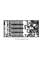
Page 19: ...FF 8070 Component Layout...

Page 20: ...18 19 20 21 22 23 24 25 26 27 15 17 14 13 12 11 16 4 U43 G A 1 A 2 A 3 A 4 Y1 Y2 Y3 Y4 G A 5 A 6 A 7 A 8 Y5 Y6 Y7 Y8 19 2 17 4 15 18 3 16 5 1 6 13 8 11 14 7 12 9 74HC244 U41 G A 1 A 2 A 3 A 4 Y1 Y2 Y...

Page 21: ...PORT D W A9 R A8 A0 A7 A1 A6 A2 A5 A3 A4 REFCAS CAS3 BNK0 CAS2 BNK1 CAS0 BNK2 CAS1 BNK3 5V MEMBUS MOSI SPCK MISO RST1 SELP0 SELP1 IOA IOB IOC IOD DVRo RQ0 RQ1 RQ2 RQ3 MPT 5V 5V 6 5 7 b U47 LF353N R8 1...

Page 22: ...5 6 7 8 9 10 1 1 5Kx9 RP1 CAS00 CAS01 CAS02 CAS03 CAS04 CAS05 CAS06 CAS07 BNK0 BNK1 BNK2 BK3b BK3a G A 1 A 2 A 3 A 4 Y1 Y2 Y3 Y4 G A 5 A 6 A 7 A 8 Y5 Y6 Y7 Y8 19 2 17 4 15 18 3 16 5 1 6 13 8 11 14 7 1...

Page 23: ...6 7 8 9 10 1 RP3 1 5Kx9 CAS20 CAS21 CAS22 CAS23 CAS24 CAS25 CAS26 CAS27 BNK0 BNK1 BNK2 BK3b BK3a G A 1 A 2 A 3 A 4 Y1 Y2 Y3 Y4 G A 5 A 6 A 7 A 8 Y5 Y6 Y7 Y8 19 2 17 4 15 18 3 16 5 1 6 13 8 11 14 7 12...

Page 24: ...he center of the power audio cable The end of this wire has a molex crimp pin installed with a short section of heat shrink tubing to prevent it from shorting to adjacent circuitry This wire can eithe...

Page 25: ...The battery backup cable provides a DB 9 connection for an external battery DB 9 pinout 1 BATT 8 12V 2 n c 3 n c 4 n c 5 n c 6 BATT 7 BATT 8 BATT 9 BATT...

Reviews: