

A
A
B
B
C
C
D
D
E
E
F
F
G
G
H
H
1
1
2
2
3
3
4
4
5
5
6
6
FF Systems
jmh
jmh
6/30/95
6/30/95
F
P.O. Box 5533 512-
365-1120
(v)
Round Rock, TX 78683
[email protected]
www.rollanet.org/~joeh/
12/14/02
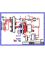
SHT 2 OF 4
R E V :
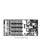
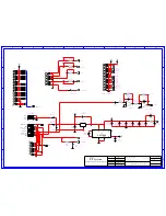
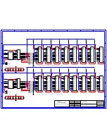
FF-8070 D.V.R.
CW out
"Affordable Repeater Control Solutions"
Systems
FF
8070.schem
B
Rel. date
chk'd by
Des. chk
D a t e
D r a w n
by
P a g e
s i z e
T I T L E :
B(+)
B(-)
B(-)
CMD lock
GND
GND
+12V in
MAIN in
DVR out
AUX in
1
2
3
4
5
6
7
8
9
10
11
12
13
14
15
16
17
18
19
20
21
22
23
24
25
26
P1
MEM EXP
1
2
3
4
5
6
7
8
9
10
11
12
13
14
15
16
17
18
19
20
P4
MULTI-PORT
D
~W
A9
~R
A8
A0
A7
A1
A6
A2
A5
A3
A4
REFCAS
~CAS3
BNK0
~CAS2
BNK1
~CAS0
BNK2
~CAS1
BNK3
+5V
MEMBUS
MOSI
SPCK
MISO
~RST1
SELP0
SELP1
IOA
IOB
IOC
IOD
DVRo
~RQ0
~RQ1
~RQ2
~RQ3
~MPT
+5V
- 5 V
-
+
6
5
7
b
U47
LF353N
R8
10K
R7
20K
R9
5.1K
-
+
2
3
1
a
U47
LF353N
C34
100pF
C35
100pF
C1-
C1+
VO
OSC
Vcc
FC
GND
LV
ICL7660
2
4
8
1
5
7
3
6
U51
1
2
3
U45
LM7805
C52
100uF
C51
330uF
T
P6KE15
Z1
D2
1N4001
D1
1N4001
1
2
3
4
5
6
7
8
9
P3
DVR I/O
1
2
3
P2
BATTERY
~SECUR
DVo
C53
100uF
-5V
~Sreset
~RST1
MISO
SPCK
MOSI
aaud
C56
100uF
C57
10uF
C58
10uF
C59
10uF
0.1uF
C55
+5V
1uF
C33
0.1uF
C54
10
R21
0.1uF
C60
+5d
1N4735
D3
330
R24
RP5res
D6
1N4001
C61
10uF
R10
10K
+12V
D4
1N4001
DVi
1
2
3
4
5
6
7
8
9
10
P3a
DVR I/O
100
R32
100
R33
100
R34
R35
n/u
1
2
3
4
5
6
7
8
9
10
SPI Bus
P5
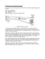
Summary of Contents for FF-8070
Page 19: ...FF 8070 Component Layout...


