


FF-8070 Legacy Installation Supplement
For FF-8070 units that are manufactured for FF-800 revE or F controllers, the following cables are
provided:
One (1) power/audio cable
One (1) battery backup cable
One (1) SPI cable
One (1) Female DB-9 (solder type) w/ metalized hood
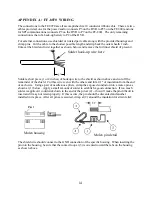
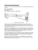
POWER/AUDIO Cable pictorial
The FF-8070 should be installed adjacent to the FF-800 (the P7 side). Install the DVR P3
connector and the FF-800 P25 connector. Remove the existing FF-800 P1 connector and install
the daisy chain connector from the DVR cable. Re-install the existing power connector on the top
of the DVR daisy chain connector.
The FF-8070 ~CMD unlock signal is provided as an unconnected wire that is coiled and secured
near the center of the power/audio cable. The end of this wire has a molex crimp pin installed with
a short section of heat shrink tubing to prevent it from shorting to adjacent circuitry. This wire can
either be connected to the FF-800 P5 connector (one of the logic outputs), to a user supplied
switch, or left as is (if no DVR security code is desired).
If the ~CMD unlock signal is connected to the FF-800 P5, use the associated logic output to allow
programming of the DVR security code. The FF-800 logic output commands should be placed in
sysop secure mode (see the FF-800 manual for details on configuring the FF-800 logic output
commands to require control unlock security).
If there are any connections to the FF-800 P7, remove the existing connection and install the
supplied ribbon cable. Move the existing P7 connection to the DVR P5a connection. The other
end of the DVR ribbon cable goes to FF-8070 P5.
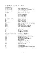
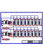
Summary of Contents for FF-8070
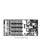
Page 19: ...FF 8070 Component Layout...


