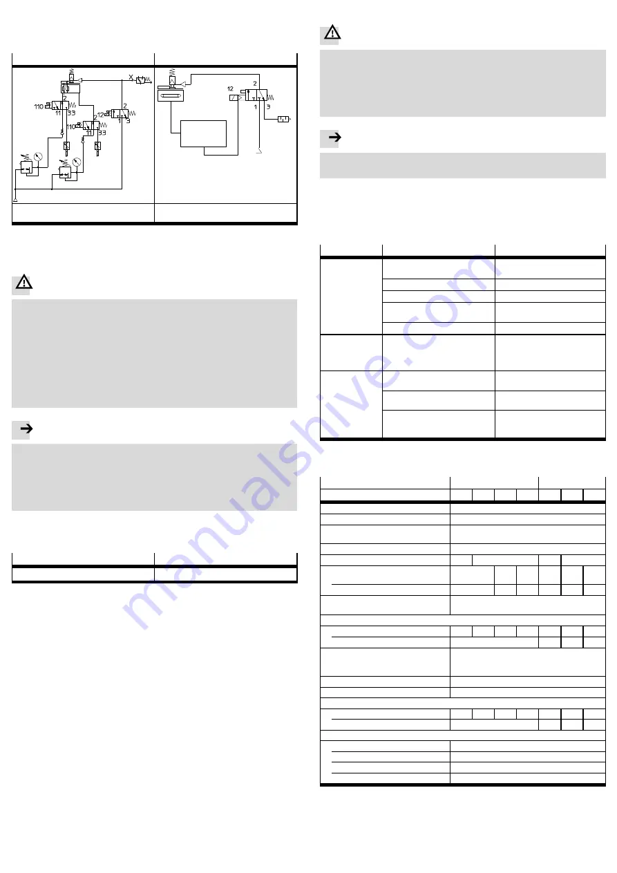
• Connect the tubing of the clamping unit and the cylinder with the directional
control valves intended for this purpose.
The following shows two examples of control circuits.
DGC
EGC
CMMP-AS
Out A/Out B
1)
Valve control DGC(I) with clamping unit
(e.g. clamps in case of sudden pressure failure)
Valve control EGC with clamping unit at the
controller CMMP-AS
1)
depending on configuration
Fig. 3
5
Commissioning
Warning
Uncontrolled moving parts can cause injury to people in the vicinity of the linear
drive.
• Make sure that, after pressurization of the clamping unit, no uncontrolled
movements can occur at the linear drive.
No movement may be triggered in the case of a jammed clamping unit, since
otherwise excessive wear will occur on the clamping unit. If a movement oc-
curs with a jammed clamping unit, the proper function of the clamping unit
must be checked, since excessive wear has probably occurred.
• Make sure that, in the traversing area, no one can reach into the direction of
motion of the moving loads and that no foreign bodies can get in.
Note
The actuators may perform sudden unexpected movements.
• Consider that the specified technical data of the clamping unit must not be
exceeded.
In the case of DGC(I)-25/32 and EGC-80, the clamping unit is not suitable for
braking (
Technical data).
The dynamic forces must not exceed the static holding forces.
• Observe the commissioning instructions in the DGC(I)/EGC operating
instructions.
• Pressurize the clamping unit as follows:
For releasing the clamp
For clamping the slide
4.5
1)
... 8 bar
pressureless
1)
Lower pressures will impair or prevent the release of the clamp hold
2)
Hoses that are too long or hose cross sections that are too small between the valve and clamping unit
delay clamping and opening.
Fig. 4
6
Operation
If there is a change in the effective load:
• Comply with the safe loads (
Technical data).
Checking the clamp hold:
• Check regularly or after a sudden power failure through a brake test to make
sure that clamping is secure without an effective load:
1. Make sure that the axis is at rest.
2. Vent the clamping unit.
3. Pressurize the clamping unit with the test force through the axis for at least
5 seconds. The test force corresponding to the risk assessment must equal
at least the nominal force of the application.
The maximum movement must be within the tolerance window. This tolerance
window must be determined in the risk assessment.
With all applications:
• Protect the guide rail against contamination.
7
Disassembly and repair
Warning
Danger of injury! Preloaded springs can throw the spring casing
7
outward dur-
ing dismantling.
Loss of holding force! Loosening of the cover
2
causes the factory setting of the
clamping force to be lost. The slide will then possibly be held with reduced
clamping force or not at all.
• Make sure that the cover
2
and the spring casing
7
are
not
dismantled.
Note
The actuators may perform sudden unexpected movements.
• Make sure that the linear drive is deactivated and the clamping unit exhausted.
• Send the product to our repair service if required.
This will ensure that special attention is given to the necessary fine tuning
and testing. The clamping unit does not usually require maintenance.
8
Troubleshooting
Malfunction
Possible cause
Remedy
Slide moves even
though clamping
unit is exhausted
Operating pressure is applied, since
the valve or air vent is defective
Check valve and air vent
Load too large
Reduce the load
Contamination of the guide rail
Clean guide rail
Control of the axis movement
defective
Check control of the linear axis and
eliminate the error.
Wear
Send to Festo
Slide clamped
even though
clamping unit is
pressurized
Insufficient operating pressure on
the clamping unit
Increase operating pressure
(
Technical data)
An unexpected
movement takes
place after the
clamping unit is
released.
In the case of EGC with spindle drive:
motor active and moves the axis
Check activation of the motor
controller
Piston of the DGC(I) always runs
against an unpressurized chamber
Always run against a pressurized
chamber (
DGC(I) commissioning)
Forces not balanced (e.g. through
large applied load with vertical
installation)
Create balanced forces to the
extent possible
Fig. 5
9
Technical data
Type
DGC(I)-...-1H-PN
EGC-...-...H...-PN
Size
25
32
40
50
80
120
185
Design
Spring-loaded clamping profile
Reliable component
in accordance with DIN EN ISO 13849
Clamping type
Clamping through spring,
Loosening through compressed air
Operating medium
Compressed air to ISO 8573-1:2010 [7:4:4]
Pneumatic connection
M3
M5
M3
M5
Max. number of emergency
brakings
1)
–
750
750
–
750
750
with reference energy
[Nm]
–
35
35
–
35
70
Actuating time
(releasing/clamping)
[ms]
100 (only clamping unit)
Static holding force
...-1H...-PN
[N]
320
500
1200
1200
320
1200
1500
...2H-PN
[N]
–
640
2400
3000
Max. axial movement during
clamping and releasing of the
clamping unit
[mm]
0.2
Ambient temperature
[°C]
–10 ... +60
Operating pressure
[bar]
4.5 ... 8
Moving applied load (clamping unit)
...-1H...-PN
[kg]
0.7
0.9
3.2
3.9
0.7
2.3
4.9
...2H-PN
[kg]
–
1.3
4.0
8.3
Materials (clamping unit)
Housing, cover, clamping jaws
Coated steel
Piston
Polyacetal
Spring
Spring steel
Seals
Nitrile rubber, polyurethane
1)
Emergency braking is a braking of the effective load in case of power failure at the drive axis
Fig. 6


