7
Operation
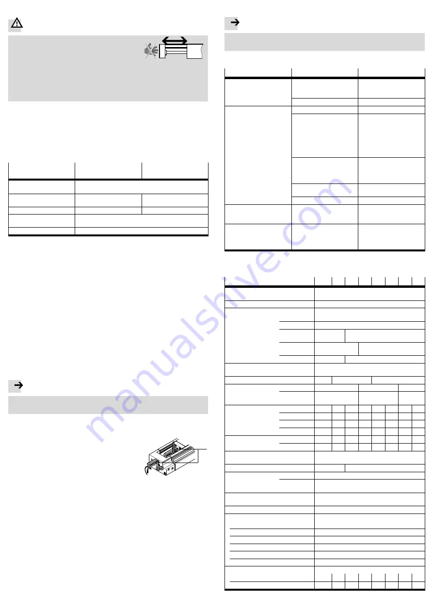
Warning
Make sure that in the travel range of the drive
– Nobody can reach into the path of the movable
components (e.g. by providing a protective
guard).
– There are no foreign objects (e.g. hexagon
wrench when setting the end position under
pressure).
It must not be possible to touch the drive until
the moveable mass has come to a complete rest.
Fig. 26
8
Maintenance and care
Cleaning:
Exhaust the DGSL.
Clean the DGSL if required with a soft, damp cloth. Use non-abrasive cleaning
agents.
Lubricate the following components of the DGSL:
Component
Ungreased surfaces of
the piston rod
Roller bearing of the
slide
Lubrication interval
As required (e.g. after cleaning), otherwise the DGSL is
maintenance-free
Reason for lubrication
Humidity protection and
gliding quality
Gliding quality
Lubricating point
Piston rod
Guide rail
Lubricating procedure
Push the slide backwards and forwards by hand when
lubricating (even distribution of grease)
Lubricating grease
LUB-KC1 from Festo (
è
Spare parts catalogue at www.festo.com)
Fig. 27
Check to see if more frequent lubrication is required. This may be the case with:
– High temperatures
– strong accumulation of dirt
– fat solvent fluids or vapours in the vicinity.
Check the cushioning components
1
every 2 million cycles for signs of wear
(e.g. abrasion, oil leakage, ...).
Replace the cushioning elements if there are signs of wear, at the latest after
every 5 million cycles (keep clamping component in a safe place when dismant
ling the DGSL).
9
Repair and disassembly
Exhaust the complete system and the device.
Recommendation: Send the product to our repair service.
This way, the fine tuning and tests that are required will be taken into particular
consideration.
Note
In particular, attempting to repair the slide guide yourself is strongly discour
aged.
Information about spare parts and aids can be found at:
www.festo.com/spareparts.
To replace the integrated cushioning components
1
:
Observe the section “Precision adjustment of the
end positions” in the chapter “Commissioning”.
Fig. 28
aE
Proceed as follows:
1. Loosen the clamping component
aE
on the cushioning component (clamping
component can fall out).
2. Replace cushioning component (
è
Accessories at www.festo.com/catalogue).
– DYEF-S-…-Y1 at
DGSL-…-E
– DYEF-…-Y1 at
DGSL-…-P
– DYEF-…-Y1F
at DGSL-…-P1
– DYSW-…-Y1F
at DGSL-…-Y3
– DYSW-…-Y1F
at DGSL-…-Y11
3. Carry out the precision adjustment of the end positions (
è
6 Commissioning).
10
Accessories
Note
Please select the corresponding accessories from our catalogue
(
è
www.festo.com/catalogue).
11
Troubleshooting
Malfunction
Possible cause
Remedy
Uneven movement of the
moving mass
One-way flow control valve not
installed correctly
Check the flow control
functions (supply or exhaust
air flow control)
Bearing surfaces dirty
Clean the bearing surfaces
Hard impact at the end posi
tion
Speed too high
Reduce speed
no or too low cushioning
– Adjust shock absorber/
fixed stop again (
è
6.1 Pre
paration of commissioning)
– Reduce speed
– Check and, if necessary, re
place cushioning compon
ents
Missing air cushion
Simultaneous pressurization
of both compressed air supply
ports with subsequent ex
hausting of one side
Shock absorber defective
(only for DGSL-…-Y3)
Replace shock absorbers
(
è
Effective load too large
Reduce effective load
Slide in initial position despite
pressurization
Tubing connection error
– Check blanking plug
– Checking the tubing con
nection
The slide speed is too low
– Pressurization cross-sec
tional area too small
– Flow control valves set in
correctly
Check pressurization cross-
sectional area and adjustment
of throttle
Fig. 29
12
Technical data
DGSL
4
6
8
10
12
16
20
25
Design
Double-acting drive with yoke kinematics and ball-
bearing cage guide
Mounting position
Any
Cushioning
E/P
Flexible cushioning, without metal end stop, both
ends
P1
Flexible cushioning, with metal end stop, both ends
Y3
–
With progressive shock absorber,
both ends
Y11
–
With progressive shock ab
sorber, both ends
N
–
Without cushioning
Operating medium
Compressed air in accordance with
ISO8573-1:2010 [7:4:4]
Operating pressure
[bar]
2.5 … 8 1.5 … 8
1 … 8
Pneumatic connection
M3
M5
G
x
N
–
M5 suitable for
10-32 UNF
x
NPT
Impact energy in the end
positions
E/P
[Nm]
0.015
0.05
0.08
0.12
0.25
0.35
0.45
0.55
P1
[Nm]
0.005
0.02
0.03
0.04
0.06
0.12
0.2
0.25
Y3
[Nm]
–
–
0.5
1
2
4
7
10
Y11
[Nm]
–
–
–
0.5
1
2
4
7
Theoretical force
at 6 bar
Advance [N]
17
30
47
68
121
188
295
483
Return
[N]
13
23
40
51
104
158
247
415
Max. permissible forces
and torques
è
Catalogue specifications:
www.festo.com/catalogue/dgsl
Max. speed
[m/s] 0.5
0.8
Repetition accuracy
E/P
[mm]
0.3
P1/Y3/
Y11
[mm]
±0.01
Ambient temperature
[°C]
0… 60 (observe temperature range of proximity
sensors)
Note on materials
Free of copper and PTFE
Information on material
Housing, cover, yoke plate
Anodised wrought aluminium alloy
Screws
Steel
Piston rod, slide, adjusting screw
High-alloy stainless steel
Cover, stops, driver
Beryllium bronze, nickel-plated
Buffer
Nitrile rubber
Seals
Hydrated nitrile rubber, polyurethane
Weight
[kg]
Min. stroke
0.08
0.16
0.24
0.4
0.6
0.9
1.5
2.5
Max. stroke
0.1
0.23
0.45
0.8
1.5
2.0
4.3
6.1
Fig. 30


