7 / 48
Festo 7DGE_25-63_ZR_KFb_en
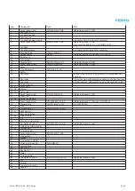
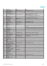
2.2
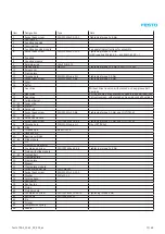
Types and part numbers
Type
Part number
DGE-25-…-ZR
193742
DGE-40-…-ZR
193743
DGE-63-…-ZR
193744
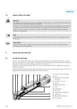
The complete overview of features, accessories, type
codes, technical data and dimensions for the toothed belt
axes DGE-… -ZR can be found in the product catalogue or
on the Festo website (
www.Festo.com
).
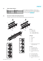
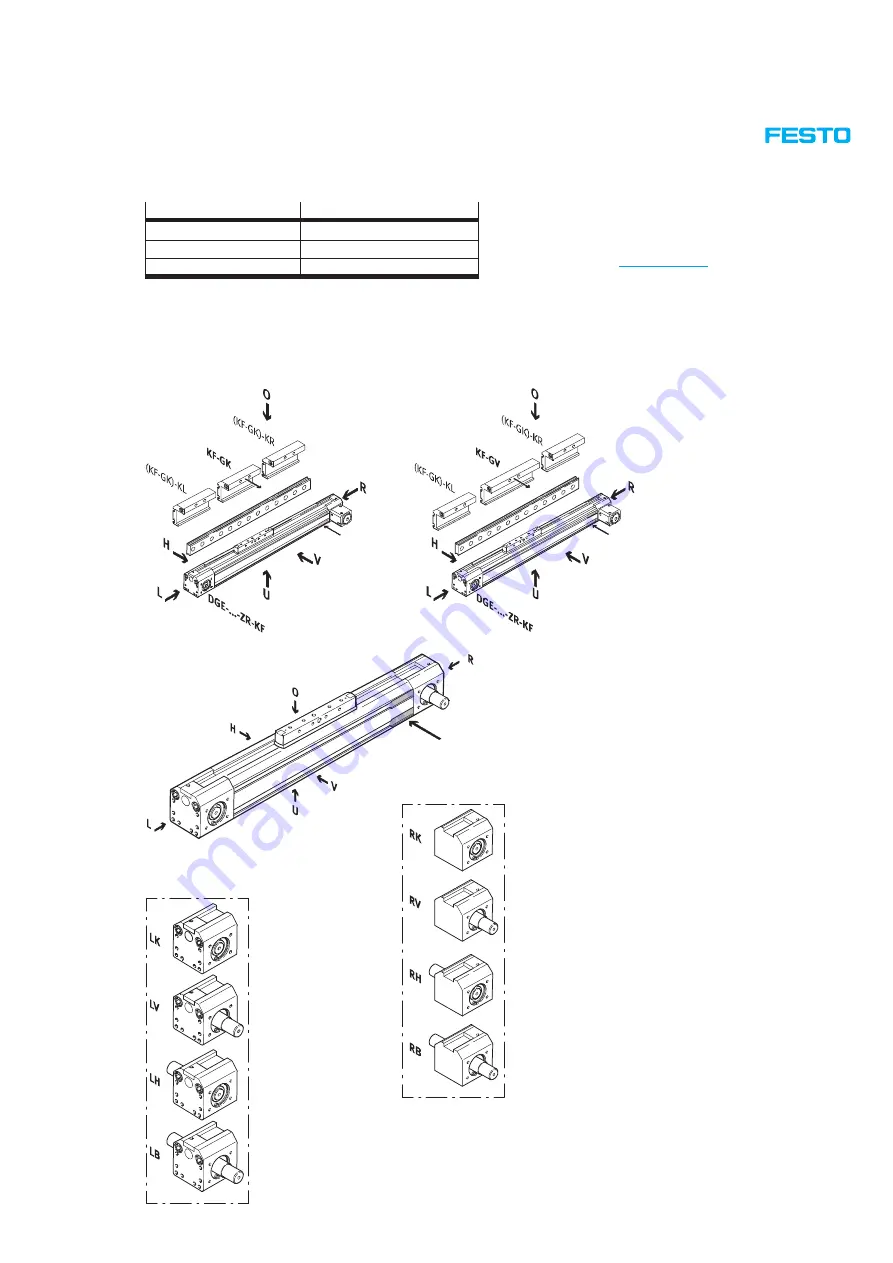
2.3
Overview of variants and mounting directions
This diagram provides an overview of the mounting directions and variants for the toothed belt axis.
-H-
-H-
-H-
Drive shaft on left
Drive shaft on right
Versions:
GK = Standard slide
GV = Extended slide
…-KL = Additional slide on left
…-KR = Additional slide on right
Orientation:
O = Top
U = Underneath
R = Right
L = Left
V = Front
H = Rear
-H- = Position of the insertion points
for proximity sensors
Drive shaft:
LK = No drive shaft on left
LV = Drive shaft on left, front
LH = Drive shaft on left, rear
LB = Drive shaft on left, front and
rear
RK = No drive shaft on right
RV = Drive shaft on right, front
RH = Drive shaft on right, rear
RB = Drive shaft on right, front and
rear
Summary of Contents for DGE-25 ZR RF Series
Page 47: ......
Page 48: ......
Page 49: ...Operating instructions en Toothed belt pretension test equipment 7Tension01_TBb_en...


