4.1
Scope of delivery
Component
Number
Servo drive CMMT-AS-...
1
Operating instructions CMMT-AS-...
1
Tab. 6: Scope of delivery
4.2
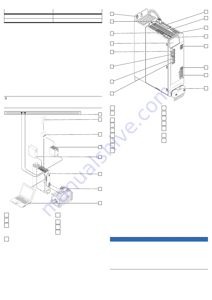
System structure
The servo drive CMMT-AS is a 1-axis servo drive. Depending on the product
variant, the following components, which are necessary for standard applications,
are integrated into the device or into the cooling profile of the device:
–
Mains filter (guarantees immunity to interference and limits conducted emis-
sions)
–
Electronics for DC link voltage conditioning
–
Power stage (for motor control)
–
Braking resistor (integrated into the cooling element)
–
Brake chopper (switches the braking resistor in the DC link circuit, if and when
required)
–
Temperature sensors (for monitoring the temperature of the power module and
of the air in the device)
–
Fan in the cooling profile
The servo drive features a real-time Ethernet interface for process control. Var-
ious bus protocols are supported depending on the product design (EtherCAT,
EtherNet/IP or PROFINET).
The device can be parameterised via a PC using either the real-time Ethernet
interface or the separate standard Ethernet interface.
Festo recommends use of servo motors, electromechanical drives, lines and
accessories from the Festo accessory programme.
1
2
3
4
5
6
7
8
Fig. 1: System structure (example)
1
Bus/network
2
Main switch
3
Automatic circuit breaker/fuses
and all-current-sensitive RCD
(residual current device)
(optional)
4
Fixed power supply for logic
voltage supply 24 V DC (PELV)
5
External braking resistor
(optional)
6
Servo drive CMMT-AS
7
Servo motor (here EMME-AS)
8
PC with Ethernet connection for
parameterisation
4.2.1
Overview of connection technology
1
2
3
4
5
6
7
8
9
10
11
12
13
14
15
16
Fig. 2: Connections of the CMMT-AS-C7/C12-11A-P3 (example)
1
PE connection, housing
2
[X9A] Mains and DC link circuit
connection
3
[X9C] Logic voltage
4
[XF2 OUT] RTE interface port 2
5
[XF1 IN] RTE interface port 1
6
[X1C] inputs/outputs for the axis
7
[X6B] motor auxiliary connection
8
[X6A] motor phase connection
9
Shield clamp of motor cable
10
[X2] encoder connection 1
11
[X3] encoder connection 2
12
[X10] device synchronisation
13
[X18] standard Ethernet
14
[X5] connection for operator unit
(behind the blind plate)
15
[X1A] I/O interface
16
[X9B] connection for braking
resistor
4.3
Safety sub-functions
4.3.1
Function and application
The servo drive CMMT-AS-...-S1 has the following safety-related performance fea-
tures:
–
Safe torque off (STO)
–
Safe brake control (SBC)
–
Safe stop 1 (SS1) with use of a suitable external safety relay unit and appro-
priate wiring of the servo drive
–
Diagnostic outputs STA and SBA for feedback of the active safety sub-function
4.3.2
Safety sub-function STO
Function and application of STO
The safety sub-function STO switches off the driver supply for the power semi-
conductor, thus preventing the power output stage from supplying the energy
required by the motor. The power supply to the drive is safely disconnected
when the safety sub-function STO is active. The drive cannot generate torque and
so cannot perform any dangerous movements. With suspended loads or other
external forces, additional measures must be put in place to prevent movements
being performed (e.g. mechanical clamping units). In the STO state, the standstill
position is not monitored.
The machines must be stopped and locked in a safe manner. This especially
applies to vertical axes without automatic locking mechanisms, clamping units or
counterbalancing.
NOTICE
If there are multiple errors in the servo drive, there is a danger that the drive will
move. Failure of the servo drive output stage during the STO status (simultaneous
short circuit of 2 power semiconductors in different phases) may result in a
limited detent movement of the rotor. The rotation angle/travel corresponds to a
pole pitch. Examples:
• Rotating motor, synchronous machine, 8-pin
è
Movement
<
45° at the motor
shaft
• Linear motor, pole pitch 20 mm
è
Movement
<
20 mm at the moving part
STO request
The safety sub-function STO is requested on 2 channels by simultaneously
switching off the control voltage at both control inputs #STO-A and #STO-B.
STO feedback via STA diagnostic contact
The status of the safety sub-function STO can be reported to the safety relay unit
via the STA diagnostic output.


