8.3
Commissioning steps
NOTICE
Unwanted drive movements or damage to components.
Incorrect parameterisation may result in unwanted drive movements or overload
when the closed-loop controller is enabled or may lead to connected components
becoming overloaded or damaged.
• Do not enable the closed-loop controller until the configured components
(servo drive, motor, axis, etc.) match those that are connected exactly.
During initial commissioning with the Festo Automation Suite with the CMMT-AS
plug-in installed, the following steps must be performed, for example:
1. Perform configuration and parameterisation with the CMMT-AS plug-in (hard-
ware configuration, critical limits and parameters).
2. If the safety function is being used, check functioning of the safety functions
è
Manual Safety sub-function.
3. Check signal behaviour of the digital inputs/outputs (e.g. limit/reference
switch).
4. Provide required control signals.
5. Check direction of rotation/direction of travel of the electromechanical drive
(e.g. in jog operation).
6. Carry out homing.
7. Test positioning behaviour (test mode,
è
help for the CMMT-AS plug-in).
8. If necessary, optimise controller setting (optional,
è
help for the CMMT-AS
plug-in).
9. Perform fieldbus configuration and test control profile (
è
description of the
device profile used).
10. Complete commissioning (e.g. save project with Festo Automation Suite and
archive project).
9
Operation
Check the safety functions at adequate intervals for proper functioning. It is the
responsibility of the operator to choose the type and frequency of the checks
within the specified time period. The manner in which the test is conducted
must make it possible to verify that the safety device is functioning perfectly in
interaction with all components. Time period for cyclical test
data, safety engineering.
The CMMT-AS is maintenance-free during its period of use and specified service
life. The test interval varies from one safety sub-function to another:
–
STO: no test has to be carried out during the period of use, but we recommend
evaluating STA whenever the sub-function is requested to ensure maximum
diagnostic coverage and the highest safety-related classification.
–
SBC: cyclical test required at least once every 24 h and SBA evaluation rec-
ommended whenever the sub-function SBC is requested to ensure maximum
diagnostic coverage and the highest safety-related classification.
10
Maintenance and care
If used as intended, the product is maintenance-free.
10.1
Cleaning
WARNING
Risk of injury from electric shock.
Contact with live parts at the power connections [X6A], [X9A] and [X9B] can result
in severe injuries or death.
• Do not pull out power supply plugs while live.
• Before touching, wait at least 5 minutes after switching off the load voltage to
allow the intermediate circuit to discharge.
•
Clean the outside of the product with a soft cloth.
11
Malfunctions
11.1
Diagnostics via LED
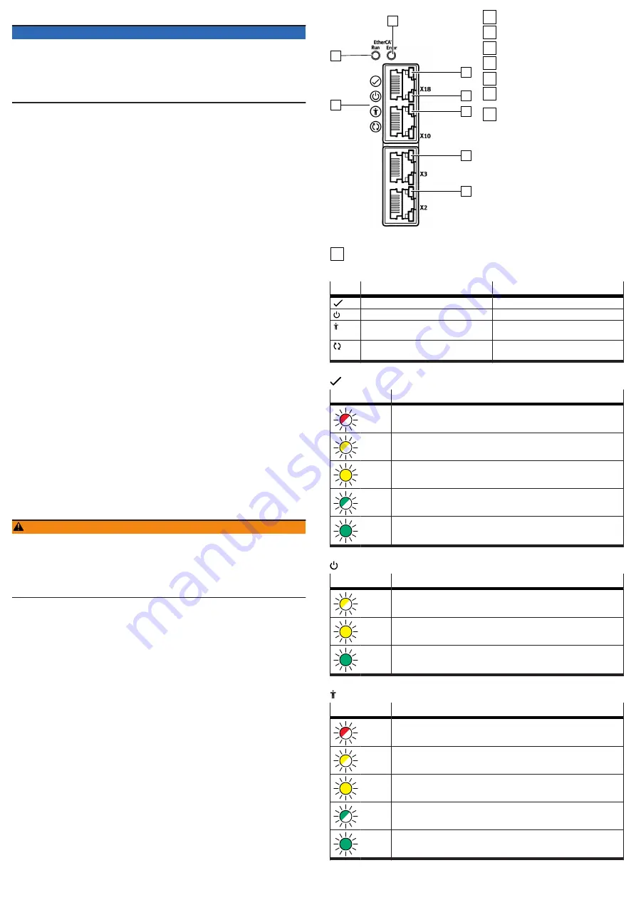
On the front and top of the device, there are some LEDs for indicating status
information. The number of LEDs depends on the product design. Up to 11 LEDs
are located on the front of the device. Up to 4 LEDs are located on the top of the
device at the connections [X19], XF1 IN and XF2 OUT.
The following image shows an example of the LEDs on the front of product variant
CMMT-AS-...-EC. The labelling and function of the Run LED and Error LED vary
according to the product variant.
1
2
3
4
5
6
7
8
Fig. 11: LEDs on the front
1
Device status (4 LEDs)
2
Run (example CMMT-AS-...-EC)
3
Error (example CMMT-AS-...-EC)
4
Ethernet interface activated [X18]
5
Communication activity [X18]
6
Sync interface activated [X10]
7
Encoder status, encoder interface
[X3]
8
Encoder status, encoder interface
[X2]
11.1.1
Device status displays
LED
Designation
Brief description
Status LED
Indicates the general device status
Power LED
Indicates the status of the power supply
Safety LED
Indicates the status of the safety equip-
ment
Application status LED
Indicates the identification sequence and is
reserved for future extensions
Tab. 45: Device status LEDs (status, power, safety and application status LEDs)
Status LED, display of the device status
LED
Meaning
Flashes
red
An error is present.
Flashes
yellow
A warning is present, or the servo drive is currently performing a firmware
update.
Illumi-
nated
yellow
The servo drive is in the initialisation phase.
Flashes
green
The servo drive is ready, and the power stage is switched off (Ready).
Illumi-
nated
green
The power stage and the closed-loop controller are enabled.
Tab. 46: Status LED
Power LED, status of the power supply
LED
Meaning
Flashes
yellow
The logic voltage and AC supply are present. The intermediate circuit is being
charged.
Lights
up
yellow
The logic voltage supply is present, but the AC supply is lacking.
Lights
up
green
The logic voltage supply is present, and the intermediate circuit is charged.
Tab. 47: Power LED
Safety LED, status of the safety engineering
LED
Meaning
Flashes
red
Error in the safety part or a safety condition has been violated.
Flashes
yellow
The safety sub-function has been requested but is not yet active.
Illumi-
nated
yellow
The safety sub-function has been requested and is active.
Flashes
green
Power stage, brake outputs and safety diagnostic outputs are blocked (safety
parameterisation is running).
Illumi-
nated
green
Ready, no safety sub-function has been requested.
Tab. 48: Safety LED


