


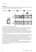


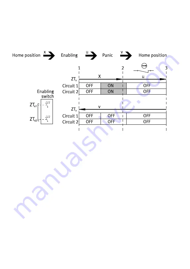
Panic actuation
When the actuating elements are pressed to the panic position, the switching element is mechanically
designed so that the enabling position is skipped when it is released:
Fig. 6 Switching path diagram for panic actuation
Category 4 PL e in accordance with EN ISO 13849-1 for the relevant safety function can be reached
with the use of the 3-position enabling switch on two electrical circuits and a suitable dynamic monit-
oring with the actuation cycles with reference to the B
10D
value of the safety devices.
In accordance with EN 60204-1, the 3-position enabling switch must be implemented in such a way
that in position 1 (switch off function - the control element is not actuated) and position 3 (Off function
- the control element is pressed down to the "panic position") at least one of the stop categories 0, 1
or 2 is initiated.
For the calculation of the PL of the enable safety function, the safety engineering characteristic values
(PL, PFH
D
and B
10D
values) of the involved components must be included. Details on calculating the PL
for the entire safety function
è
EN ISO 13849-1 (chapter 6.3, appendix H and appendix I.)
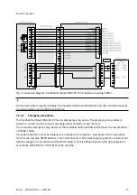
Simultaneity monitoring is required if it is not possible to exclude faults with regard to short circuits in
the enabling circuit, as otherwise an unrecognised accumulation of faults could result, which in turn
leads to a loss of safety. For example, the simultaneity monitoring can be achieved by connection to a
safety controller or to the monitoring device PilzPNOZ s6.1.
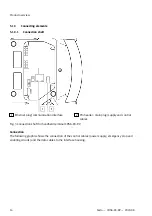
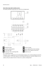
The following connection example shows how the 3-position enabling switch of the handheld terminal
CDSA-D3-RV achieves an enabling function up to category 4 PL e. The entire machine must be
designed for this purpose.
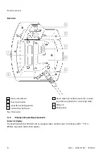
Product overview
18
Festo — CDSA-D3-RV — 2020-08


