background image

DICHIARAZIONE DI CONFORMITÁ CE DEL COSTRUTTORE

Via Del Lavoro, 4 – 40023 Castel Guelfo (BO) – ITALY

Tel. +39-0542/487611 Fax +39-0542/488226 – http://www.femi.it

FEMI S.p.A.

Dichiara sotto la propria  esclusiva responsabilità che questa macchina è conforme alle disposizioni della Direttiva Macchine


2006/42/CE

 ed è identico, in quanto incluso nell’ allegato IV della direttiva, al macchinario oggetto della certifi cazione CE di 

tipo (vedi etichetta riportata) rilasciata da ICE Istituto Certifi cazione Europea S.p.A, organismo notifi cato n. 0303. E’ inoltre 

conforme alle disposizioni delle seguenti altre direttive: 

2006/95/CE - 2004/108/CE - 2011/65/UE - 2012/19/UE

.

COMPLIANCE DECLARATION CE OF THE BUILDER 

Via Del Lavoro, 4 – 40023 Castel Guelfo (BO) – ITALY

Tel. +39-0542/487611 Fax +39-0542/488226 – http://www.femi.it

FEMI S.p.A.

Declare under our sole responsibility that the machine,to which this declaration relates, is in conformity with the regulations indicated in 

Machinery Directive 

EC/2006/42 

and is identical, in that it is included in appendix IV of the directive, to the machinery concerning CE 

certifi cation type (see relative label) issued by the ICE (Istituto Certifi cazione Europea SpA), Notifi ed Body no. 0303. Furthermore it is 

also in conformity with the following standards: 

EC/2004/108 - EC/2006/95 - 2011/65/EU - 2012/19/EU

.

CE KONFORMITATS ERKLARUNG DES HERSTELLER 

Via Del Lavoro, 4 – 40023 Castel Guelfo (BO) – ITALY

Tel. +39-0542/487611 Fax +39-0542/488226 – http://www.femi.it

FEMI S.p.A.

Erklärt unter seiner alleinigen Verantwortung, dass diese Maschine den Bestimmungen der Maschinenrichtlinie 

2006/42/

EG

 entspricht, und, insofern eingeschlossen in Anhang IV der Richtlinie, identisch mit der maschinellen Ausrüstung ist, 

die Gegenstand der EG–Baumusterbescheinigung ist (siehe das abgebildete Etikett), die vom ICE (Istituto Certifi cazione 

Europea SpA, anerkannte Prüfstelle Nr. 0303) erlassen wurde.  Sie entspricht ferner den Bestimmungen der folgenden 

weiteren Richtlinien: 

2004/108/EG - 2006/95/EG - 2011/65/UE - 2012/19/UE

.

DECLARATION DE CONFORMITE CE DU CONSTRUCTEUR 

Via Del Lavoro, 4 – 40023 Castel Guelfo (BO) – ITALY

Tel. +39-0542/487611 Fax +39-0542/488226 – http://www.femi.it

FEMI S.p.A.

Déclare, sous sa propre responsabilité, que cette machine est conforme aux dispositions de la Directive Machines  

2006/42/

CE 

et est identique, car incluse dans l’annexe IV de la directive, à la machine objet de la certifi cation CE de type (voir étiquette 

rapportée) remise par ICE Istituto Certifi cazione Europea SpA, organisme notifi é n° 0303. En outre, elle est conforme aux 

dispositions des autres directives suivantes : 

 2004/108/CE - 2006/95/CE - 2011/65/UE - 2012/19/UE

DECLARATION DE CONFORMIDAD CE DEL CONSTRUCTOR 

Via Del Lavoro, 4 – 40023 Castel Guelfo (BO) – ITALY

Tel. +39-0542/487611 Fax +39-0542/488226 – http://www.femi.it

FEMI S.p.A.

Declara bajo su exclusiva responsabilidad que esta máquina cumple con lo dispuesto por la  Directiva Máquinas  

2006/42/

CE

 y es idéntica, en cuanto máquina que fi gura en el anexo IV de la directiva, a la máquina objeto de la certifi cación CE de 

tipo (véase etiqueta ilustrada) otorgada por ICE Instituto de Certifi cación Europea SpA, organismo notifi cado nº 0303.

Asimismo, cumple también con lo dispuesto por las siguientes directivas:  

2004/108/CE - 2006/95/CE - 2011/65/UE - 

2012/19/UE

.

DECLARAÇÃO DE CONFORMIDADE CE DO CONSTRUCTOR

Via Del Lavoro, 4 – 40023 Castel Guelfo (BO) – ITALY

Tel. +39-0542/487611 Fax +39-0542/488226 – http://www.femi.it

FEMI S.p.A.

Declaramos sob a nossa exclusiva responsabilidade que esta máquina está em conformidade com as disposições da Directiva 

Máquinas  

2006/42/CE

 e que é idêntica, porque contemplada no anexo IV da directiva, ao maquinário objecto da certifi cação CE 

de tipo (ver a etiqueta indicada) emitida por ICE Istituto Certifi cazione Europea SpA, organismo notifi cado nº 0303. Está também 

em conformidade com as disposições das seguintes directivas:  

2004/108/CE - 2006/95/CE - 2011/65/UE - 2012/19/UE

.

Persona autorizzata a costituire il fascicolo tecnico

Person authorized to create the technical fi le

Zur Ausarbeitung der technischen Dokumentation bevollmächtigte Person

Personne autorisée à établir le dossier technique

Persona autorizada a crear el documento técnico

Pessoa autorizada a constituir o fascículo técnico

MAURIZIO CASANOVA

Via Del Lavoro, 4 - Castel Guelfo

Castel Guelfo (BO), 25/03/2011

Summary of Contents for 1050 3D

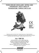
Page 1: ...DE UTILIZA O CERTIFICATA CERTIFIED GEPR FT CERTIFIE CERTIFICADA CERTIFICADA TRONCATRICE CIRCOLARE MITRE SAW KREISS GE SCIE A ONGLET TRONZADORA SERRA CIRCULAR Art 1050 3D www femi it CONSERVARE PER UT...

Page 2: ...UR Via Del Lavoro 4 40023 Castel Guelfo BO ITALY Tel 39 0542 487611 Fax 39 0542 488226 http www femi it FEMI S p A D clare sous sa propre responsabilit que cette machine est conforme aux dispositions...

Page 3: ...nistra 215 x 90 mm Taglio inclinato a 45 a sinistra 165 x 65 mm Taglio composto trasversale e inclinato a 45 a sinistra 45 x 70 mm Sporgenza massima lama piano superiore 60 mm Arresti di taglio destra...

Page 4: ...mente vietato rimuovere qualsiasi ritaglio o altre parti del pezzo in lavorazione dall area di taglio mentre la macchina in moto e la testa di taglio in posizione di lavoro PERSONALE AUTORIZZATO ALL U...

Page 5: ...i legati al funzionamento della lama in rotazione nell uso come troncatrice e della lama di taglio nell uso con pianetto Questi rischi sussistono durante le fasi di lavoro di manutenzione e di ricerca...

Page 6: ...alimentazione secondo le specifiche riportate sul presente documento e sulla targhetta del motore ATTENZIONE Una volta collegato accertarsi che il cavo di alimentazione sia completamente appoggiato a...

Page 7: ...pia inclinazione rotazione pi inclinazione testa tenere il pezzo saldo alla macchina con il morsetto e guidare la discesa della testa con la mano destra Fig 28 3 3 REGOLAZIONE ALTEZZA PIANO SUPERIORE...

Page 8: ...periore necessario montare il carter di protezione inferiore in dotazione par 3 3 ATTENZIONE La macchina dotata di spintore 17 di dimensioni e forma conformi a quelle prescritte dalle norme di sicurez...

Page 9: ...banco di lavoro il quale nondeveandareperdutoodanneggiarsi altrimenti il funzionamento in modalit sega a banco non sar disponibile o gli operatori potrebbero subire infortuni inserite il perno 31 nell...

Page 10: ...pecializzato 2 Controllate se la dentatura che state usando giusta 1 Controllate qual la giusta dentatura da utilizzare Il motore non funziona Il motore parte lentamente o non raggiunge la velocit di...

Page 11: ...Crosscut at 90 305 x 90 mm Oblique cutting 45 left and right 215 x 90 mm Inclined cutting 45 left 165 x 65 mm Compound cut transversal and inclined 45 left 45 x 70 mm Upper surface maximum blade proje...

Page 12: ...running and the cutting head is in the operating position Always keep hands away from the work area when the machine is running before performing tasks of any kind release the main switch located on t...

Page 13: ...g operation maintenance and troubleshooting operations Precautions adopted The machine is tted with special safety guards designed to guarantee safety conditions throughout operation Safety standards...

Page 14: ...t the power supply cable lies completely on the ground and is not at any point raised in the air WARNING the plug provided is a European 2 pole C type plug EEC 7 1 1 9 INFORMATION ABOUT ELECTROMAGNETI...

Page 15: ...e angle cutting rotation plus head tilting hold the work piece securely to the machine using the right hand and guide the lowering of the head with the left hand Fig 28 3 3 ADJUSTMENT HEIGHT OF UPPER...

Page 16: ...nd shape of which are in compliance with the Safety Standards When the machine is used as DISK SAW thus using the upper table for the machining operations such tting MUST ABSOLUTELY be used Hold pushe...

Page 17: ...the guard it is no longer possible to use the saw in workbench mode and operators could be injured if the guard is not in place Insert the pin 31 in the hole provided and lock it with the knob 32 Ins...

Page 18: ...kaging indicates that the product must be disposed of separately from ordinary household waste when it reaches the end of its working life 7 TROUBLESHOOTING 1 Have the machine checked by skilled perso...

Page 19: ...m 90 Querschnitt 305 x 90 mm 45 Gehrungsschnitt rechts und links 215 x 90 mm 45 Neigungsschnitt links 165 x 65 mm Kombinierter Schnitt quer und geneigt bei 45 links 45 x 70 mm Max berstand des S gebla...

Page 20: ...te Schuhe tragen Verwenden Sie das Werkzeug das in diesem Handbuch empfohlen wird So erreichen Sie dass Ihre Kreiss ge optimale Leistungen erbringt Die f r Wartung oder Einstellung verwendeten Schl ss...

Page 21: ...diesen nicht auf andere Personen Restrisiko mechanischer Art Schergefahr Schnitt und Trenngefahr Quetschgefahr Einzugs und Fanggefahr Ursprung des Restrisikos An der Trennmaschine verbleiben Restrisi...

Page 22: ...chung der Versorgungsspannung mit denAngaben in diesem Dokument und auf dem Motorschild ACHTUNG Vergewissern Sie sich nach dem Anschluss dass das Stromkabel am Boden liegt und nicht angehoben ist um e...

Page 23: ...t doppelter Neigung Drehung plus Kopfneigung das Werkst ck mit der rechten Hand fest gegen die Maschine dr cken und mit der linken Hand den Kopf bei seiner Abw rtsbewegung f hren Abb 28 3 3 H HENEINST...

Page 24: ...che gearbeitet muss die mitgelieferte untere Schutzabdeckung montiert werden Abschn 3 3 ACHTUNG Die Maschine ist mit einer den einschl gigen Sicherheitsvorschriften 17 entsprechenden Schubvorrichtung...

Page 25: ...ht m glich ist und die Bediener verletzt werden k nnten Den Zapfen 31 in die vorgesehene Bohrung einstecken und mit dem Drehknopf 32 feststellen Die Klemme auf dem Zapfen 31 einschieben und mit dem Dr...

Page 26: ...Altger t von anderen Abf llen getrennt entsorgt werden muss 7 ST RUNGSSUCHE UND BEHEBUN 1 Maschine vom Fachmann berpr fen lassen Nie Motor selbst reparieren Gefahr 2 Sicherungen kontrollieren event A...

Page 27: ...biseau 45 G 165 x 65 mm Coupe compos e 45 G 45 G 45 x 70 mm D passement maximum de la lame plan sup rieur 60 mm But e d onglet D G 0 15 22 5 30 45 But e d inclinaison 0 e 45 Laser conform ment la nor...

Page 28: ...que la machine fonctionne et que la t te de coupe est en position de travail PERSONNEL AUTORISE A UTILISER LA MACHINE La machine a t con ue et construite pour tre utilis e par un personnel quali ayant...

Page 29: ...e scie et de la lame de coupe lors de l utilisation avec plan Ces risques subsistent pendant les phases de travail de maintenance et de recherche des pannes Pr cautions adopt es La machine est quip e...

Page 30: ...imentation repose compl tement au sol et non en hauteur afin d viter les risques de buter sur ce dernier ATTENTION la che fournie en quipement est de type C CEE 7 17 europ enne 2 p les 1 9 INFORMATION...

Page 31: ...N Lors de la coupe double inclinaison rotation plus inclinaison t te maintenez la pi ce sur la machine de la main droite et guidez la descente de la t te de la main gauche Fig 28 3 3 REGLAGE DE LA HAU...

Page 32: ...rieur il faut monter le carter de protection inf rieur livr avec la machine par 3 3 ATTENTION La machine est quip e d un pousseur 17 dont les dimensions et les formes respectent les indications fourn...

Page 33: ...doit pas tre perdu ou d t rior sinon le fonctionnement en mode scie banc ne sera plus disponible ou les op rateurs risquent des accidents Introduire le goujon 31 dans le trou correspondant et le bloqu...

Page 34: ...de sa dur e de vie utile 7 GUIDE A LA LOCALISATION DES PANNES 1 Faites contr ler la machine par un personnel sp cialis Ne cherchez pas r parer vous m me le moteur cela pourrait tre dangereux 2 Contr l...

Page 35: ...quierda 165 x 65 mm Corte compuesto transversal e inclinado en 45 a izquierda 45 x 70 mm Parte sobresaliente m xima cuchilla plano superior 60 mm Tope de corte derecha e izquierda 0 15 22 5 30 45 Tope...

Page 36: ...emente prohibido quitar cualquier recorte o partes de la pieza que se est trabajando desde el rea de corte mientras la m quina est en movimiento y la cabeza de corte est en posici n de trabajo PERSONA...

Page 37: ...otaci n en el uso como tronzadora y de la cuchilla de corte en el uso con plano Estos riesgos subsisten durante el trabajo el mantenimiento y la localizaci n de causas de aver a Precauciones adoptadas...

Page 38: ...ue el cable del alimentaci n quede completamente depositado sobre el pavimento no debe quedar elevado a n de evitar posibles riesgos residuales de tropezar con el mismo ATENCI N El enchufe suministrad...

Page 39: ...el corte de doble inclinaci n rotaci n m s inclinaci n cabezal mantener la pieza jada rmemente en la m quina con la mano derecha y guiar la bajada del cabezal con la mano izquierda Fig 28 3 3 REGULACI...

Page 40: ...n par 3 3 ATENCI N La m quina est dotada de un dispositivo de empuje 17 cuyas dimensiones y forma respetan las exigidas por las normas de seguridad Cuando la m quina se usa como SIERRA CIRCULAR utiliz...

Page 41: ...o podr utilizarse el funcionamiento en modalidad sierra de banco o los operadores podr an sufrir accidentes Introduzcan el perno 31 en el ori cio correspondiente y bloqu enlo con el bot n 32 Introduzc...

Page 42: ...rio efectuar su recogida selectiva y diferenciada del resto de residuos urbanos 7 GU A PARA LA LOCALIZACI N DE LAS AVER AS 1 Haga que personal especializado controle la m quina No intente reparar pers...

Page 43: ...mposto transversal e inclinado a 45 esquerda 45 x 70 mm Sali ncia m xima da l mina plano superior 60 mm Limitadores de corte direito e esquerdo 0 15 22 5 30 45 Limitadores de inclina o 0 e 45 Laser co...

Page 44: ...a a manuten o e a regula o tenham sido removidas da m quina antes de arrancar Assegurar se de que a velocidade indicada na l mina seja ao menos igual velocidade indicada na m quina TERMINANTEMENTE PRO...

Page 45: ...e Seccionamento Enla amento Arraste e Aprisionamento Origem do risco residual Na serra de esquadria permanecem riscos residuais ligados ao funcionamento da l mina em rota o durante o uso como serra de...

Page 46: ...TEN O A cha el ctrica fornecida do tipo C CEE 7 17 europ ia de 2 polos 1 9 INFORMA O SOBRE COMPATIBILIDADE ELECTROMAGN TICA As regras europeias de seguran a e em particular a Directiva 2004 108 CE con...

Page 47: ...direita e acompanhe a descida da cabe a com a m o esquerda Fig 28 3 3 AJUSTAMENTO DA SUPERF CIE DE TRABALHO SUPERIOR Fig 11 21 SOMENTE POR SERRA CIRCULAR ATEN O Quando trabalhar na superf cie superio...

Page 48: ...imento radial no nal do curso posterior por meio do bot o 3 Eleve a cabe a da m quina o mais alto poss vel Segure na pe a de trabalho firmemente contra os suportes angulares da base com a sua m o esqu...

Page 49: ...r rio o funcionamento na modalidade de serra de bancada n o ser poss vel ou os operadores podem sofrer acidentes Introduzir o perno 31 no respectivo furo e x lo com o puxador 32 Introduzir o torno no...

Page 50: ...outros rejeitos 7 CORREC O DE PROBLEMAS 1 Mande a m quina ser observada por um t cnico especializado N o tente reparar a m quina porque pode ser perigoso 2 Verifique os fus veis e substitua os se nece...

Page 51: ...ransformer Laser Laser switch Motor Soft Start QS1 TC1 HL1 QS2 M S EN QS1 TC1 HL1 QS2 M S Schalter Transformer Laser Laser Schalter Motor Soft Start Interrupteur Transformateur Laser Interrupteur de L...

Page 52: ...6 90 15 18_Rev D 40023 CASTEL GUELFO BO ITALY Via Del Lavoro 4 Tel 39 0542 487611 Fax 39 0542 488226 E Mail infocom femi it www femi it...

Reviews: