


SMART SN TRANSMITTER – OPERATING INSTRUCTIONS
MU2B-0328GE51 R0207A
7
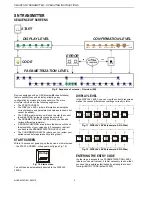
CODE
NOT
VALID
Put code
0000
OK
-
+
0
Put code
0000
-
+
8
Put code
0000
-
+
9
Put code
0009
-
+
0
Put code
0009
-
+
1
Put code
0009
-
+
4
Put code
0009
-
+
5
ESCAPE
OK
OK
LEFT
LEFT
LEFT
OK
OK
OK
OK
Put code
0000
-
+
1
OK
LEFT
LEFT
LEFT
LEFT
LEFT
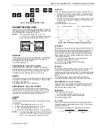
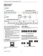
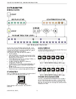
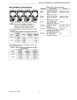
Fig. 13. Entering the ENTRY CODE
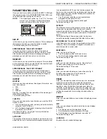
PARAMETRIZATION LEVEL
Once you have successfully entered the ENTRY CODE and
thus gained access to the PARAMETRIZATION LEVEL, you
can edit values and reconfigure the device.
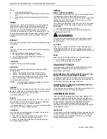
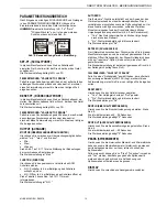
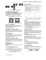
NOTE:
The currently set option (e.g. "yes," "no,"
"4…20 mA", etc.) is always marked in the display
screen with a small dot to the left (see Fig. 5).
Function
N.O.
OK
N.C.
ESCAPE
Function
N.O.
N.C.
ESCAPE
OK
DOT
Fig. 14. Dot indicating present setting
START-PT.
In this screen, you can select the start-point. This is defined
as the pressure at which you want the device to begin
providing an analog output signal.
The default setting is "0".
ERROR MESSAGE: "VALUE OUT OF RANGE"
If you have entered a start-point outside of the device's
specified pressure measurement range or which is for any
other reason not rational, this error message will appear,
whereupon you should then enter a correct value.
END-PT.
In this screen, you can select the end point. This is defined as
the pressure at which you want the device to stop providing
an analog output signal.
The default setting is 100% of full-scale.
ERROR MESSAGE: "VALUE OUT OF RANGE"
If you have entered an end-point outside of the device's
specified pressure measurement range or which is for any
other reason not rational, this error message will appear,
whereupon you should then enter a correct value.
OUTPUT
MODE
Here, you can set the device's mode. Four different modes
are possible:
•
0…10V: the voltage range is set to 0…10 V;
•
0…20mA: the current range is set to 0…20 mA;
•
2…10V: the voltage range is set to 2…10 V;
•
4…20mA: the current range is set to 4…20 mA (default).
NOTE:
The only mode supported by the SN 2-Wire Trans-
mitter is "4…20 mA". However, it can be inverted
to "20…4 mA" (see section "Function" below).
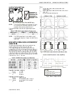
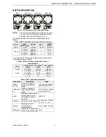
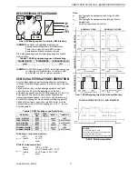
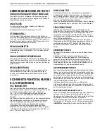
FUNCTION
Here, you can invert the device's function (see also Fig. 15):
•
Non-invert.: the mode (current range or voltage range, as
the case may be) is set to 0/4…20 mA or 0/2…10 V (as
the case may be) (default);
•
Inverted: the mode (current range or voltage range, as the
case may be) is set to 20…0/4 mA or 10…0/2 V (as the
case may be).
The default setting is "non-invert."
U
/I
MAX MAX
U
/I
MAX MAX
U /I
MIN MIN
U /I
MIN MIN
output U/I
output U/I
NORMAL OPERATION
INVERTED OPERATION
pressure
pressure
pressure
start
pressure
start
pressure
end
pressure
end
Fig. 15. SN Transmitter output (normal/inverted)
AUTO ZERO
The purpose of the auto zero function is to allow the user to
adjust the device to local ambient atmospheric pressure and
to compensate for drift. To use this function properly, the
device must be mounted in the application and the pressure
sensor exposed to local ambient atmospheric pressure (i.e.
0 bar relative pressure).
•
Yes: The device takes the current local ambient
atmospheric pressure as its zero.
•
No: The device setting remains unchanged.
The default setting is "No".
SET ZERO
The difference between the pressure value you enter in this
screen and the pressure which the device is currently
measuring will be taken as the offset. This offset can be reset
to zero using the reset zero option (see section "Reset Zero"
below).
The default setting is the pressure which the device is
currently measuring (meaning that the offset is then zero).
ERROR MESSAGE: "VALUE OUT OF RANGE"
If you have set a zero outside the permissible range (±25%
full-scale), this error message will appear, whereupon you
should then enter a correct value.
RESET ZERO
Here, you can reset the zero:
•
Yes: The pressure offset will be set to zero.
•
No: The device setting remains unchanged.
The default setting is "No".
ATT. FILTER
Here, you can attenuate (dampen) the outputted portion of
the peak. Possible values range from 0 to 99%. The default
setting is "10" percent.
The formula for calculating the attenuation is as follows:
1
100
)
100
1
(
−
+
−
=
n
n
n
y
n
attenuatio
x
n
attenuatio
y