


SMART DCM SWITCH – OPERATING INSTRUCTIONS
MU2B-0328GE51 R0207A
3
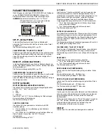
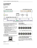
PARAMETRIZATION LEVEL
Once you have successfully entered the ENTRY CODE and
thus gained access to the PARAMETRIZATION LEVEL, you
can edit values and reconfigure the device.
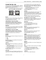
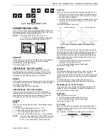
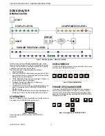
NOTE:
The currently set option (e.g. "yes," "no," "window
monitor", etc.) is always marked in the display
screen with a small dot to the left (see Fig. 5).
Monitor
Max.
OK
Window
ESCAPE
Monitor
Max.
Window
ESCAPE
OK
DOT
Fig. 5. Dot indicating present setting
SET-PT.
In this screen, you can select the set-point. This is defined as
the pressure at which you want the device to switch.
The default setting is 60% of full-scale.
ERROR MESSAGE: "VALUE OUT OF RANGE"
If you have entered a set-point outside of the device's
specified pressure measurement range or which is for any
other reason not rational, this error message will appear,
whereupon you should then enter a correct value.
RESET-PT.
In this screen, you can select the reset-point. This is defined
as the pressure at which you want the device to switch back.
The default setting is 40% of full-scale.
ERROR MESSAGE: "VALUE OUT OF RANGE"
If you have entered a reset-point outside of the device's
specified pressure measurement range or which is for any
other reason not rational, this error message will appear,
whereupon you should then enter a correct value.
OUTPUT
MONITOR
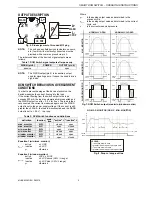
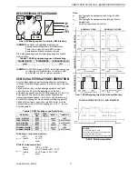
Here, you can choose between three types of monitors: min.,
max., and window.
•
Min.;
•
Max.;
•
Window;
See Fig. 7 on page 5 for an explanation of the meanings of
these different settings.
The default setting is "Max."
FUNCTION
Here, you can choose the type of action you want the DCM
Switch to have:
•
N.O.: Normally-open switch (meaning: when the switch is
activated, it will CLOSE); or
•
N.C.: Normally-closed switch (meaning: when the switch
is activated, it will OPEN).
See Table 2 and Fig. 7 on page 5 for more information.
The default setting is "N.O."
AUTO ZERO
The purpose of the auto zero function is to allow the user to
adjust the device to local ambient atmospheric pressure and
to compensate for drift. To use this function properly, the
device must be mounted in the application and the pressure
sensor exposed to local ambient atmospheric pressure (i.e.
0 bar relative pressure).
•
Yes: The device takes the current local ambient
atmospheric pressure as its zero.
•
No: The device setting remains unchanged.
The default setting is "No".
SET ZERO
The difference between the pressure value you enter in this
screen and the pressure which the device is currently
measuring will be taken as the offset. This offset can be reset
to zero using the reset zero option (see section "Reset Zero"
below).
The default setting is the pressure which the device is
currently measuring (meaning that the offset is then zero).
ERROR MESSAGE: "VALUE OUT OF RANGE"
If you have set a zero outside the permissible range (±25%
full-scale), this error message will appear, whereupon you
should then enter a correct value.
RESET ZERO
Here, you can reset the zero:
•
Yes: The pressure offset will be set to zero.
•
No: The device setting remains unchanged.
The default setting is "No".
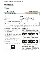
DROP-IN
Here, you can select the drop-in value. See also Fig. 8.
Possible values range from 0 to 99 seconds.
The default setting is "0" seconds.
DROP-OUT
Here, you can select the drop-out value. See also Fig. 8.
Possible values range from 0 to 99 seconds.
The default setting is "0" seconds.
PEAKS
Here, you can view the historical max. and min. measured
pressures as well as the max. measured temperature
(historical = measured since the device has been put into
operation / since the last time the peaks were cleared).
If desired, by proceeding to "Clear" and choosing "yes," you
can also permanently erase all such values. All such peaks
will then be erased and the recording of peaks will be re-
initiated.
DISPLAY
Here, you can select/alter various modes of displaying screen
information.
UNIT
Here, you can choose the units in which the device displays
pressures:
•
bar: All pressures will be displayed in bars.
•
Pa: All pressures will be displayed in Pascals.
•
Psi: All pressures will be displayed in pounds / in
2
.
The default setting is "bar".
LANGUAGE
English is the only supported language.