


SMART DCM SWITCH / SN TRANSMITTER – OPERATING INSTRUCTIONS
MU2B-0328GE51 R0207A
10
REMARKS AS PER EN 61010-1
PREREQUISITES FOR MOUNTING
The unit is not suitable for mounting in explosive environ-
ments.
The unit may be operated only within the specified technical
limits.
CONNECTION
In the case of units with stationary mounting, the following
requirements must be observed:
Minimum cross-sectional diameter of wiring: 0.75 mm
2
POWER FAILURE
In the event of a power failure, the device will cease
operation. After power is returned, the device will, after a brief
(2-3 sec) initialization period, resume normal functioning.
Because its memory is stored on EPROM, no re-
parametrization is necessary.
CLEANING AGENTS
All commercial cleaning agents approved for use in the food
industry and for stainless steel 1.4571 are permitted.
MISUSE OF UNIT
Installing/operating this device contrary to these Operating
Instructions can impair its proper functioning / result in
malfunctioning and device damage - result in danger of injury.
RECALIBRATION
It is not possible to recalibrate the device in the field, nor does
it contain any field-reparable parts. For recalibration or repair,
contact FEMA.
SAFETY FUNCTION (D.C. SUPPLY,
ONLY)
SN TRANSMITTER
Measuring pressures is the safety function of the direct-
current-driven devices. It is applicable for 2-wire (4…20 mA)
and 3-wire versions (0/4…20 mA and 0/2…10 V with auxiliary
WARN output) and ensures an accuracy of 5% of the
measured value within this range.
The safety function ensures that, in the worst-case scenario,
the diagnosis function responds within 45 seconds.
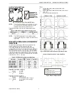
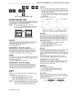
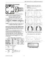
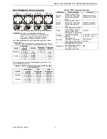
The transmitter's output is updated according to Fig. 15 on
page 7. The X-axis of the characteristic indicates the
measured pressure after application of the offset com-
pensation and the attenuation filter. The Y-axis displays the
generated output in the range according to the output
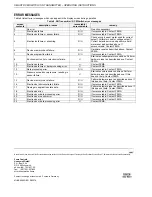
definition (see Fig. 15 on page 7 and Table 5 on page 9).
DCM SWITCH
Measuring pressures is the safety function of the direct-
current-driven devices. The device will act within an accuracy
of 5% as a Max., Min., or Window monitor (switch output and
auxiliary WARN output), depending upon the device settings.
The switch output is in the "open" state (see Table 7)
whenever the prerequisites for the "open" state are fulfilled.
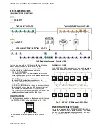
ERROR STATES
While the device is in operation, it provides continuous
supervision. The diagnostics detect errors in the application
(e.g. when the desired output signal is not reached), in the
electronics (e.g. in the event of miswiring or defective
circuitry), as well as sensor defects and runtime errors in the
software.
If an error occurs, it will be signalized on the signal output
and/or WARN output within a maximum of 45 seconds, and
the display illumination will turn RED and remain RED until
the error has been eliminated.
There are two classes of errors: recoverable errors and
unrecoverable errors.
RECOVERABLE ERRORS
Recoverable errors can be solved by a software reset:
After the error is recognized, it is reported at the signal output
and the WARN output for 5 seconds. After that, the device
performs an automatic software reset (i.e. the signal output
will go into the start-up condition and the device will be re-
initialized). The device will then resume normal operation.
UNRECOVERABLE ERRORS
If (after an automatic software reset) the error is still detected
or it recurs during the next 10 minutes of operation, the error
is reclassified as unrecoverable. This means that it cannot be
resolved without interaction of the user. If, however, the error
does not recur within 10 minutes, the device will resume
normal operation.
Unrecoverable errors can be resolved only by means of a
hardware reset. A hardware reset is performed by
disconnecting the device from the power supply for at least 10
seconds.