


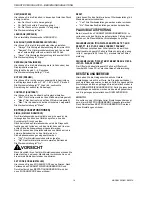

SMART DCM SWITCH – OPERATING INSTRUCTIONS
MU2B-0328GE51 R0207A
2
DCM SWITCH
SEQUENCE OF SCREENS
MONITOR
FUNCTION
OUTPUT
SET-PT
RESET-PT
AUTO-0
SET ZERO
RESET 0
PRESSURE,
STATE
SET-PT.
WELCOME
RESET-PT.
MONITOR
FUNCTION
DROP-IN
DROP-OUT
MESSAGE
MESSAGE
DROP-IN
DROP-OUT
PEAKS
UNIT
LANGUAGE
BACKLIGHT
REFRESH
ROTATE
CONTRAST
DISPLAY
CLEAR
MIN.
MAX. TEMP.
SIMUL.
SET CODE
RESET
EXTRAS
ENTER
CODE
GO TO
CONFIRM
ALL
SETTINGS
PLAUSIBLE
?
NO
YES
SET-PT.
RESET-PT.
MONITOR
FUNCTION
DROP-IN
DROP-OUT
CODE
SIMUL.
STORING...
DISPLAY LEVEL
PARAMETRIZATION LEVEL
CODE
ERROR
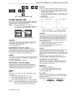
START
CONFIRMATION LEVEL
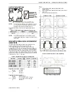
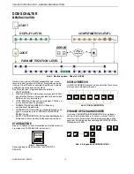
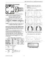
Fig. 1. Sequence of screens - Overview (DCM)
Devices equipped with an HMI (
H
uman-
M
achine-
I
nterface)
feature pushbuttons and a display, allowing easy
configuration by means of a menu structure. The menu
structure is divided into the following segments:
•
The START SCREEN;
•
The DISPLAY LEVEL (where information including the
current pressure and parameterized values are shown but
cannot be edited);
•
The CODE area (where you will have to enter the correct
four-digit CODE in order to proceed any further);
•
The PARAMETRIZATION LEVEL (where you can edit
various different parameters);
•
A ERROR-CHECKING area (where the device will check
the plausibility of your values and, if necessary, redirect
you back to the PARAMETRIZATION LEVEL); and
•
The CONFIRMATION LEVEL (where you can review your
edited values before permanently storing them).
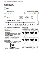
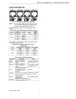
START SCREEN
Within 10 seconds of powering-up the device, an initial screen
– the START SCREEN - will appear briefly (see Fig. 2).
Startup
Fig. 2. Start screen
You will then be automatically directed to the DISPLAY
LEVEL.
DISPLAY LEVEL
In the DISPLAY LEVEL, you can view the current pressure as
well as the various different user-settings currently in force.
Reset-pt.
Monitor
Function
Drop in
delay
0s
Drop
out delay
0s
4.00bar
Window
N.C.
MENU
MENU
MENU
MENU
MENU
-0.90
bar
Closed
MENU
NE
XT
PREV
IO
US
NE
XT
NE
XT
NE
XT
NE
XT
NE
XT
PREV
IO
US
PREV
IO
US
PREV
IO
US
PREV
IO
US
PREV
IO
US
Set-pt.
5.00bar
MENU
NE
XT
PREV
IO
US
ESCAPE
ESCAPE
ESCAPE
ESCAPE
ESCAPE
ESCAPE
Fig. 3. DISPLAY LEVEL
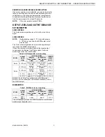
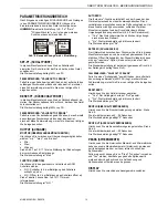
ENTERING THE ENTRY CODE
In order to gain access to the PARAMETRIZATION LEVEL
(where you can edit values), it is first necessary to show that
you have the requisite authorization by entering the correct
four-digit ENTRY CODE (default: 0000).
CODE
NOT
VALID
Put code
0000
OK
-
+
0
Put code
0000
-
+
8
Put code
0000
-
+
9
Put code
0009
-
+
0
Put code
0009
-
+
1
Put code
0009
-
+
4
Put code
0009
-
+
5
ESCAPE
OK
OK
LEFT
LEFT
LEFT
OK
OK
OK
OK
Put code
0000
-
+
1
OK
LEFT
LEFT
LEFT
LEFT
LEFT
Fig. 4. Entering the ENTRY CODE