


SMART DCM SWITCH / SN TRANSMITTER – OPERATING INSTRUCTIONS
MU2B-0328GE51 R0207A
11
REMEDYING AN UNRECOVERABLE ERROR SETTING
If an unrecoverable error is indicated, you can try to solve the
issue by powering down the device and eliminating the error
conditions (e.g. miswiring, overtemperature, overpressure).
A hardware reset is performed by disconnecting the device
from the power supply for at least 10 seconds.
NOTE:
If the error persists, contact FEMA.
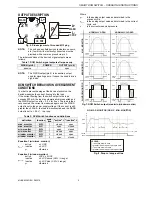
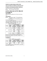
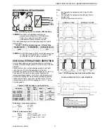
OUTPUT LEVELS AND OUTPUT BEHAVIOR
SN TRANSMITTER
2-WIRE VERSION
The 2-wire version signalizes an error via the current loop
signal.
3-WIRE VERSION
NOTE:
If
either analog range 0…10 V or analog range
0…20 mA is used, then the WARN output must
also be used.
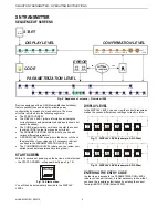
The 3-wire version signalizes an error via the signal output
(pin 4) and the WARN output (pin 2).
If (due to miswiring or electronic failure) the signal output
cannot reach the desired "high" failure state, it will auto-
matically go to the "low" failure state.
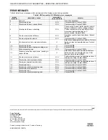
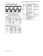
Table 6. SN Transmitter error reporting
error reporting
device
output
signal
range
primary,
"high" failure
state
secondary,
"low" failure
state
WARN
output
(pin 2)
2-wire 4…20
mA
loop current >
21 mA
loop current <
3.6 mA
NOTE 1
0…20 mA
output >
21 mA
output = 0 mA
NOTE 2
< 0.5 V
4…20 mA
output >
21 mA
output <
3.6 mA
< 0.5 V
0…10 V
output > 11 V
output = 0 V
NOTE 2
< 0.5 V
3-wire
2…10 V
output > 11 V output < 1.5 V < 0.5 V
NOTE 1: The 2-Wire Transmitter has no WARN output.
NOTE 2: This a valid signal; it is therefore necessary to use
the WARN output.
DCM SWITCH
Table 7. DCM Switch error reporting
error reporting
device
output
signal
range
primary,
"high" failure
state
secondary,
"low" failure
state
WARN
output
(pin 2)
switch
open /
closed
open
open*
< 0.5 V
*It is still necessary to use the WARN output to cover blocked
closed output transistor error.