


SMART DCM SWITCH – OPERATING INSTRUCTIONS
MU2B-0328GE51 R0207A
5
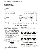
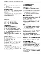
OUTPUT DESCRIPTION
1
2
4
3
L+
L-
OC PNP
1
2
3
4
P
L+
L-
OC PNP
WARN
WARN
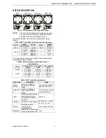
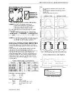
Fig. 6. Pin assignment of A-coded M12 plug
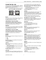
NOTE:
The unit and any field devices (actuators, sensors,
etc.) to which it is electrically connected must be
provided with a common ground via pin 3.
The initial conditions of the device's signal outputs are as
follows:
Table 1. DCM Switch signal outputs after power-up
WARN (pin 2)
POWER
OUTPUT (pin 4)
passive -- open
NOTE:
The WARN output (pin 2) is an auxiliary output
used for signaling errors. It cannot be used to drive
high loads.
DCM SWITCH BEHAVIOR IN OVERCURRENT
CONDITIONS
In order to prevent damage of the device electronics, the
device measures the current flowing into the load.
If the current flowing from the switch output to the load
exceeds 250 mA, the load is automatically disconnected and
the WARN output is set to < 0.5 V for 5 sec. The load is then
reconnected, the current is measured again, and the WARN
output is set to the power supply voltage. If the current is still
greater than 250 mA, the load is disconnected and the WARN
output is set to < 0.5 V… in a loop.
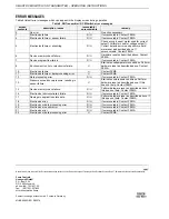
Table 2. DCM Switch functions and definitions
definition
function
equa-
tion
"active" = "inactive" =
max. monitor
N.O.
1 closed open
max. monitor
N.C.
1 open closed
min. monitor
N.O.
1 open closed
min. monitor
N.C.
1 closed open
window monitor
N.O.
2 closed open
window monitor
N.C.
2 open closed
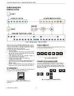
Equation 1 (min./max. monitor):
active x
≥
USP
y
n+1
= inactive
x
≤
LSP
y
n
otherwise
Equation 2 (window monitor):
active LSP
≤
x
≤
USP
inactive x
≤
LSP minus (0.5%
±
range)
Inactive x
≥
LSP plus (0.5%
±
range)
y
n+1
=
y
n
otherwise
Where
y
n
is the analog output value as determined in the
previous cycle,
y
n+1
is the analog output value as determined in the current
cycle, and
x
is the current measured pressure.
USP
USP
USP
LSP
LSP
LSP
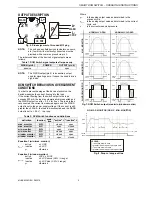
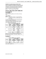
NORMALLY-OPEN
NORMALLY-CLOSED
time
time
time
p
p
p
closed
closed
closed
open
open
open
time
time
time
p
p
p
closed
closed
closed
open
open
open
USP
USP
USP
LSP
LSP
LSP
M
A
X.
MONI
T
O
R
MI
N.
MONI
T
O
R
WIND
OW MONI
T
O
R
Fig. 7. DCM Switch output (max./min./window monitor)
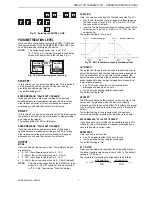
USP
LSP
time
p
closed
open
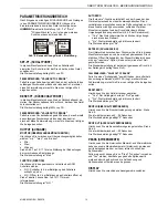
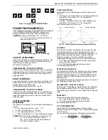
N.O. MAX. MONITOR (OR N.C. MIN. MONITOR)
T
1
T
3
T
2
T
4
LEGEND:
T less than drop-in time
T greater than or equal to drop-in time
T less than drop-out time
T greater than or equal to drop-out time
1
2
3
4
Fig. 8. Drop-in / drop-out time