background image

OBID

®


classic-pro


Manual 

ID CPR30.xx 


FEIG ELECTRONIC GmbH 

Page 41 of 126 

H01114-0e-ID-B.docx 


5.5. [0x66] Get Reader Info 

This protocol allows you to determine, a lot of Firmware and hardware options and version from the 
reader. Most information's are only required for service and support questions. 

Host   Reader 

7...8 

STX 

(0x02) 

MSB 

ALENGTH 

LSB 

ALENGTH 

COM-ADR 

[0x66] 

MODE 

CRC16 


MODE: 

Via the Parameter MODE different information could be requested from the Reader. 

0x00: 

General hard- and firmware information's 

0x04: 

Additional firmware functionality 

0x05: 

Bootloader version information. 

0x11: 

SAM Information 

0x12: 

CPU Information 

0x80: 

Device-ID: Necessary Information's for firmware updates and firmware upgrades. 


Host   Reader 

Depending on the MODE Parameter the reader response has a differing structure with sev-
eral information. 


Summary of Contents for OBID classic-pro Series

Page 1: ...MANUAL preliminary public B 2011 08 18 H01114 0E ID B doc ID CPR30 xx RFID Reader for ISO IEC14443 A B NFC and ISO IEC15693 Up From Firmware Version 01 02 00...

Page 2: ...Adam Dunkels and the Swedish Institute of Computer Science All rights reserved Redistribution and use in source and binary forms with or without modification are permitted provided that the following...

Page 3: ...with these bit spaces are reserved for future extensions or for internal testing and manufacturing functions These bit spaces must not be changed as this may cause faulty op eration of the Reader The...

Page 4: ...ecommended to use 14 2 3 3 Protocol Elements 15 2 3 4 Timing Conditions 16 2 3 5 CRC16 Calculation Algorithm for Protocol Frames 16 3 Configuration Parameters CFG 17 3 1 CFG0 RFU Reserved for Future U...

Page 5: ...onse Data ISO 14443B TR TYPE 0x05 53 6 1 1 3 Response Data ISO15693 TR TYPE 0x03 54 6 1 1 4 Sequences of Inventory Command and ISO14443 Transponder 55 6 1 2 0x25 Select 56 6 1 3 0x02 Stay Quiet 60 6 1...

Page 6: ...106 8 3 1 EM4135 EM MICROELECTRONIC 106 8 3 2 Fujitsu MB89R116 107 8 3 3 Fujitsu MB89R118 108 8 3 4 Infineon my d page mode 0x60 110 8 3 5 Infineon ISO Address mode 0xE0 111 8 3 6 KSW Microtec TempSen...

Page 7: ...l ID CPR30 xx FEIG ELECTRONIC GmbH Page 7 of 126 H01114 0e ID B docx Revision History of this documentation Revision Description 0 Described Firmware 01 00 00 01 02 00 Preliminary Version Changes are...

Page 8: ...eck DB data block frq Frequency FSK Frequency Shift Keying h Hour Hz Hertz ID Identification IDD Identifier Data IN Input LEN Length LOC Location LSB Least Significant Byte min Minutes ms Milliseconds...

Page 9: ...ouple of different ISO 14443 Type B memory chips Additional some reader models are available with 2 sockets for attachable Security Access Module SAM which makes it even suitable for applications with...

Page 10: ...Reader parameters to the individual requirements of the applications 2 1 Configuration and Control Commands This method of data transmission is used for Reader configuration and diagnostics The Reader...

Page 11: ...or writing data in addressed mode the UID of the Transponder has to be known This is executed by sending the command 6 1 1 0x01 Inventory If a Transpond er is located within the detection range of the...

Page 12: ...include its UID The following chart will show the necessary steps for the communication with a Transpond er in selected mode Host Terminal PC Reader Inventory to get the UID Transponder in antenna fi...

Page 13: ...er in case of a protocol frame failure The Reader supports two different Protocol frames which are the standard and the advanced proto col frame The Host Application can chose which protocol frame sha...

Page 14: ...A LSB CRC16 MSB CRC16 Host Reader 1 2 3 4 5 n 2 n 1 n LENGTH n COM ADR COMMAND BYTE STATUS DATA LSB CRC16 MSB CRC16 2 3 2 Advanced Protocol Frame recommended to use Reader Host 1 2 3 4 5 6 n 2 STX 0x0...

Page 15: ...n optional data field with variable length The number of DATA byte depends on the command The data will be sent always as MSB first if the Reader is in the ISO Host Com mand Mode CRC16 Cyclic redundan...

Page 16: ...x TR RESPONSE TIME Host Reader Character timeout Within one protocol the characters have to follow each other in intervals of maximum 12 ms max 12 ms max 12 ms max 12 ms Host Reader Char n Char n 1 Ch...

Page 17: ...cifies the location of the configuration block RAM EEPROM MODE specifies one or all configuration blocks Bit 7 6 5 4 3 2 1 0 Function LOC MODE CFGn address of configuration block The EEPROM configurat...

Page 18: ...ctive after writing saving this configuration block to RAM marked with 00 these bits or bytes are reserved for future extensions or for in ternal testing and manufactur ing functions These bits or byt...

Page 19: ...x 3 1 CFG0 RFU Reserved for Future Use The configuration block CFG0 is RFU Byte 0 1 2 3 4 5 6 Contents 0x00 0x00 0x00 0x00 0x00 0x00 0x00 Default 0x00 0x00 0x00 0x00 0x00 0x00 0x00 Byte 7 8 9 10 11 12...

Page 20: ...ADR Bus address of the Reader 0 254 for communication via the asynchronous interface Notes Do not configure address 255 Via the COM ADR 255 in the send protocol the Reader is able to be addressed at a...

Page 21: ...nd of Parity b00 no parity b01 even parity b10 odd parity b11 do not use D Number of data bits b0 8 data bits b1 do not use S Number of stop bits b0 1 stop bit b1 do not use NOTICE Changing of TRANS F...

Page 22: ...SE TIME 0 65535 100 ms NOTICE TR RESPONSE TIME has no effect for commands for Reader Configuration and Reader Control The block receive timeout of host computer must set to a value TR RESPONSE TIME RE...

Page 23: ...2 0x14 0x0005 0x04 0x00 2 sec 400 ms ONLINE STATE This Parameter defines the behavior of the signal transmitters if they are not activated by any other event Bit 15 14 13 12 11 10 9 8 Function Bit 7 6...

Page 24: ...e offline state if he had not received a command via his asynchronous interface 0 255 x 100 ms 0 25 5 sec TAGDETECT STATE This parameter defines the behavior of the signal transmitter if a new transpo...

Page 25: ...ypes that are operated by the Reader Byte 0 1 Bit 15 14 13 12 11 10 9 8 7 6 5 4 3 2 1 0 Driver 0 0 0 0 0 0 0 0 0 0 F E D 0 0 0 Default 0 0 0 0 0 0 0 0 0 0 1 1 1 0 0 0 b0 Driver for the Transponder typ...

Page 26: ...Transponder type is activated B Driver for my d proximity SLE55Rxx C Driver for NFC Tag Type 2 e g mifare Ultralight my d move etc L4 Driver for ISO14443A Part 4 compatible Transponders ISO14443 BIT...

Page 27: ...from the Transponder could be on 106 kBit s ore on the new higher Bit Rate b0 The first reception after a Bit Rate change is expected with 106 kBit s b1 The first reception after a Bit Rate change is...

Page 28: ...b0 The OPT_INFO byte in 0x01 inventory response is always set to 0 b1 The OPT_INFO byte in 0x01 inventory response includes further Infor mation s UID_ORDER only ISO14443A Transponder By means of this...

Page 29: ...ZE Default 0x00 0x00 0x00 0x00 0x00 0x00 0x04 ISO15693 MODE only ISO15693 Transponders Bit 7 6 5 4 3 2 1 0 Function 0 0 AFI NO TS 0 0 0 0 NO TS b0 16 timeslots b1 1 timeslot NOTICE Anticollision is on...

Page 30: ...0 Function Read Mode Blocksize DB Blocksize DB Blocksize Defines the block size of an ISO transponder which is not listed chapter 8 Sup ported ISO Host commands or if the transponder is used in the n...

Page 31: ...ollision Mode the Reader automatical ly sets Transponder specific communication parameters b0 disabled In this case the Reader doesn t process any anticollision procedure with the Transponders inside...

Page 32: ...ry command runs while not all UIDs of ISO14443A and ISO14443B Transponders in the detection range are read b1 The Inventory command stops if the UID of all ISO14443A or of all ISO14443B Transponders i...

Page 33: ...OBID classic pro Manual ID CPR30 xx FEIG ELECTRONIC GmbH Page 33 of 126 H01114 0e ID B docx 3 7 CFG6 15 Reserved...

Page 34: ...0x00 0x0000 0x00 0x00 0x00 0 x 5ms 0ms Byte 7 8 9 10 11 12 13 Contents 0x00 0x00 0x00 0x00 0x00 0x00 0x00 Default 0x00 0x00 0x00 0x00 0x00 0x00 0x00 PER RESET TIME ANT The timer value specifies a time...

Page 35: ...in the byte CFG ADR Host Reader 1 2 3 4 5 6 7 8 STX 0x02 MSB ALENGTH LSB ALENGTH COM ADR 0x80 CFG ADR CRC16 Host Reader 1 2 3 4 5 6 7 20 21 22 STX 0x02 MSB ALENGTH LSB ALENGTH COM ADR 0x80 STATUS 1 C...

Page 36: ...X 0x02 MSB ALENGTH LSB ALENGTH COM ADR 0x81 CFG ADR CFG REC CRC16 Host Reader 1 2 3 4 5 6 7 8 STX 0x02 MSB ALENGTH LSB ALENGTH COM ADR 0x81 STATUS 1 CRC16 CFG ADR 2 Bit 7 6 5 4 3 2 1 0 Function LOC 0...

Page 37: ...1 2 3 4 5 6 7 8 STX 0x02 MSB ALENGTH LSB ALENGTH COM ADR 0x83 STATUS CRC16 CFG ADR Bit 7 6 5 4 3 2 1 0 Function LOC MODE CFGn CFGn Memory address of the required configuration block MODE Specifies one...

Page 38: ...der 1 2 3 4 5 6 7 8 STX 0x02 MSB ALENGTH LSB ALENGTH COM ADR 0x52 0x00 CRC16 NOTICE The return protocol will only be sent if the inquiry is executed with the baud rate and ac tual parity of the Reader...

Page 39: ...ich will be reset MODE Controller 0 RF Controller 5 4 0x65 Get Software Version This protocol allows you to determine the software version of the Reader its type and the types of the Transponders whic...

Page 40: ...splays the Transponders supported by the Reader Bit 15 14 13 12 11 10 9 8 Function Bit 7 6 5 4 3 2 1 0 Function ISO 14443B ISO 14443A ISO 15693 RX BUF RX BUF is the maximum receive buffer size of the...

Page 41: ...4 5 6 7 8 STX 0x02 MSB ALENGTH LSB ALENGTH COM ADR 0x66 MODE CRC16 MODE Via the Parameter MODE different information could be requested from the Reader 0x00 General hard and firmware information s 0x0...

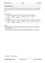
Page 42: ...mware functionality Host Reader 1 2 3 4 5 6 7 8 STX 0x02 MSB ALENGTH LSB ALENGTH COM ADR 0x66 STATUS 2 TEMPLATE FNC_LST0 9 10 11 12 13 14 15 16 17 18 19 CRC16 TEMPLATE Indicates how to interpret the f...

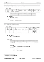
Page 43: ...6 BL_VERSION Bootloader Version BL_REV Revision of Bootloader Version 5 5 4 Mode 0x11 SAM Information Host Reader 1 2 3 4 5 6 7 8 n 3 n 2 n 1 STX 0x02 MSB ALENGTH LSB ALENGTH COM ADR 0x66 STATUS NO_OF...

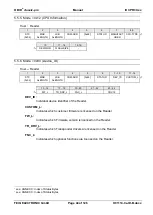
Page 44: ...14 STX 0x02 MSB ALENGTH LSB ALENGTH COM ADR 0x66 STATUS 2 DEV_ID CUSTOM_L 15 16 17 18 19 20 21 22 23 24 FW_L TR_DRV_L FNC_L CRC16 DEV_ID Individual device identifier of the Reader CUSTOM_L Indicates w...

Page 45: ...eld of the Reader will be reset to their base setting Host Reader 1 2 3 4 5 6 7 STX 0x02 MSB ALENGTH LSB ALENGTH COM ADR 0x69 CRC16 Host Reader 1 2 3 4 5 6 7 8 STX 0x02 MSB ALENGTH LSB ALENGTH COM ADR...

Page 46: ...ADR 0x6A RF_OUTPUT CRC16 Host Reader 1 2 3 4 5 6 7 8 STX 0x02 MSB ALENGTH LSB ALENGTH COM ADR 0x6A STATUS 1 CRC16 RF_OUTPUT Set on of the antenna outputs Bit 7 6 5 4 3 2 1 0 Function 0 0 0 0 0 ANT AN...

Page 47: ...a command Set Output all times that have been active until then are being overwritten by the new times included in the protocol if they are 0 Host Reader 1 2 3 4 5 6 7 STX 0x02 MSB ALENGTH LSB ALENGTH...

Page 48: ...ccepted are the time values 0 and 65535 0xFFFF see following table 0x0001 1 x 100ms 100ms 0xFFFE 65534 x 100ms 1 49 13 h 0xFFFF continuously active Notes In order to reset a continuously active time O...

Page 49: ...ted ISO Host commands are described in chapter 8 Supported ISO Host commands for each Transponder type separate 6 1 0xB0 ISO Standard Host Commands This command sends standard RF commands to the Trans...

Page 50: ...5693 TR TYPE 0x03 MODE Bit 7 6 5 4 3 2 1 0 Function MORE MORE this bit can be used to read out the whole UIDs after the Reader had signalized more data sets with status 0x94 see ANNEX C Index of Statu...

Page 51: ...der This byte represents some information s from the SAK byte as described in ISO14443 3 1 Bit 7 6 5 4 3 2 1 0 Function L4 CL3 CL3 Displays the UID length of the present Transponder b0 The UID is tran...

Page 52: ...s on the Cascade Level of the Transponder see also TR_INFO byte It is transmitted by the reader with a length of 7 or 10 byte The following table shows the structure of the UID in relation to ISO14443...

Page 53: ...is required to select the Transponder APP_DATA 4 byte Application Date according ISO 14443 3 2001 1 2 3 4 AFI CRC_B AID Number of Applications PROTO_INFO This parameter is extracted from the protocol...

Page 54: ...es DATA SETS Number of Transponder data sets to be transferred in this Reader response TR TYPE Bit 7 6 5 4 3 2 1 0 Function RF_TEC TYPE_NO RF_TEC Indicates the RFID Technology of the present Transpond...

Page 55: ...ands Response 1 no 1 possibly 6 1 2 0x25 Select Response 2 yes one Transponder on ISO14443 3 level 1 Proprietary or standard commands for ISO14443 Transponders see 6 3 0xB2 ISO14443 Special Host Comma...

Page 56: ...ly if the MODE bit CINF was set in the request and STATUS 0x00 7 8 n FORMAT CARD_INFO MODE Bit 7 6 5 4 3 2 1 0 Function 0 DRV_SEL CINF UID_LF 0 ADR ADR b001 addressed UID_LF If this bit is set the par...

Page 57: ...CTION By means of this parameter the host application explicit selects an internal driver to handle the data exchange with the addressed transponder TR DRIVER SELECTION Selected Transponder driver 0x0...

Page 58: ...ending on the Transponder type ISO 14443A 6 7 8 9 16 0x25 b000 0001 0x00 UID ISO 14443B 6 7 8 11 12 15 0x25 b000 0001 0x00 PUPI case UID_LF 1 If UID_LEN is activated the specific UID length of the Tra...

Page 59: ...der ATS 8 9 ATQA RFU Proprietary coding UID size RFU Bit frame anticollision 10 11 SAK TL 12 12 TL 2 T0 TA 1 TB 1 TC 1 T1 Tk case FORMAT 0x02 CARD_INFO contains parts of the answer ATQB response ATTRI...

Page 60: ...docx 6 1 3 0x02 Stay Quiet This command sets one Transponder to Quiet State REQUEST DATA 6 7 8 15 0x02 MODE UID MODE Bit 7 6 5 4 3 2 1 0 Function 0 0 0 0 0 ADR ADR b001 addressed UID Read only serial...

Page 61: ...Transponders REQUEST DATA 6 7 8 9 1 or 2 Bytes def by EXT_ADR 1 Byte 0x23 MODE UID BANK DB ADR DB N RESPONSE DATA STATUS 0x03 7 DB ADR E RESPONSE DATA STATUS 0x95 7 8 ISO15693 ERROR DB ADR E MODE Bit...

Page 62: ...First block number to be locked Depending on EXT_ADR First block can be any value be tween 0 and 255 or 0 and 65535 DB N Number of data blocks to be locked from the Transponder starting at DB ADR The...

Page 63: ...8 ISO15693 ERROR DB ADR E MODE Bit 7 6 5 4 3 2 1 0 Function 0 0 0 0 0 ADR ADR b000 non addressed b001 addressed b010 selected UID Read only serial number of the Transponder The UID is required only i...

Page 64: ...K DB ADR DB N RESPONSE DATA STATUS 0x95 7 ISO15693 ERROR RESPONSE DATA 7 8 9 10 n DB N DB SIZE SEC STATUS DB Repeated DB N times MODE Bit 7 6 5 4 3 2 1 0 Function 0 0 EXT_ADR 0 SEC ADR ADR b000 non ad...

Page 65: ...B N is TX BUF 10 DB Size 1 Standard Protocol TX BUF 12 DB Size 1 Advanced Protocol ISO15693 ERROR ISO15693 ERROR code of Transponder response This byte is only available if STATUS 0x95 DB SIZE Number...

Page 66: ...Bit 7 6 5 4 3 2 1 0 Function 0 0 0 0 SEC ADR ADR b000 non addressed b001 addressed b010 selected SEC Requests optional the security status of the followed data block b0 security status not requested S...

Page 67: ...TATUS Block security status of followed data block If SEC STATUS is not requested or not supported this value will return 0x00 DB Requested data block The block size is defined by DB SIZE Notes A read...

Page 68: ...1 Byte 1 Byte DB N times DB SIZE Bytes 0x24 MODE UID BANK DB ADR DB N DB SIZE DB Repeated DB N times RESPONSE DATA STATUS 0x03 7 DB ADR E RESPONSE DATA STATUS 0x95 7 8 ISO15693 ERROR DB ADR E MODE Bi...

Page 69: ...rd Protocol RX BUF 12 DB Size Advanced Protocol DB SIZE Number of bytes of one data block This value depends on the specification of the Trans ponder manufacturer see chapter Fehler Verweisquelle konn...

Page 70: ...D classic pro Manual ID CPR30 xx FEIG ELECTRONIC GmbH Page 70 of 126 H01114 0e ID B docx If an error occurred during a write command the number of the block where the error oc curred will be send to h...

Page 71: ...ands REQUEST DATA 4 5 6 13 6 14 7 15 8 16 9 n 17 n 0x24 MODE UID DB_ADR DB N DB SIZE DB Repeated DB N times RESPONSE DATA STATUS 0x03 5 DB_ADR E RESPONSE DATA STATUS 0x95 5 6 ISO ERROR DB_ADR E MODE B...

Page 72: ...on of the Trans ponder manufacturer see chapter 8 Supported ISO Host commands DB Data of the data block to be written to the Transponder The required block size is defined by DB SIZE The number of the...

Page 73: ...sets one ISO14443 3 Transponder into Halt State The supported ISO Host commands depends on the different Transponder types they are de scribed in chapter 8 Supported ISO Host commands REQUEST DATA 6...

Page 74: ...rietary ISO14443 RF commands to the Transponder Host Reader 1 2 3 4 5 6 n 2 n 1 n STX 0x02 MSB ALENGTH LSB ALENGTH COM ADR 0xB2 REQUEST DATA CRC16 Host Reader 1 2 3 4 5 6 7 n 2 n 1 n STX 0x02 MSB ALEN...

Page 75: ...host and the Transponder on ISO 14443 4 layer It is special designed for easy APDU data exchange NOTICE The maximum buffer size of the Reader for data exchange is 256 byte for data sending from Host t...

Page 76: ...100 0101 NAD INF APDU with NAD first chained block b1000 0111 CID NAD INF APDU with CID and NAD single block b1100 0111 CID NAD INF APDU with CID and NAD first chained block b1000 0000 DESLECT without...

Page 77: ...s bit a presence check to the current Transponder can be operated by the host The response includes only a status message b0 PING will not be operated b1 PING will be operated by the Reader NOTICE PIN...

Page 78: ...r parts of the command NOTICE If an error status is responded by the Reader the downlink chaining should stopped by the host If a MORE status 0x94 is responded by the Reader the host has to han dle th...

Page 79: ...n his receive timeout to a value gra ter than indicated by WTXM 6 7 8 9 10 11 STATUS PSTAT BLK_CNT WTXM FWI 0x94 0x01 0xXX 0xXX 0xXX WTXM and FWI refer to ISO 14443 4 The minimum receive timeout could...

Page 80: ...could not be fi nished because of transmission errors 6 7 STATUS ISO14443 ERROR STATUS see ANNEX C Index of Status Bytes ISO14443 ERROR Additional error code if STATUS 0x96 see ANNEX C2 ISO14443 Error...

Page 81: ...3 4 REQUEST DATA 6 7 8 10 n 2 0xBF RSP TIMEOUT FWI REQUEST BLOCK RESPONSE DATA n 2 RESPONSE DATA NOTICE The maximum buffer for the RESPOSE DATA is 256 byte FSDI 8 RSP 0 The Reader will send the comman...

Page 82: ...utomatically NOTICE If TIMEOUT 255 is chosen the Reader used the FWI as transmitted from the Transponder The value of TIMEOUT must be considered for calculating the TR RESPONSE TIME see CFG1 REQUEST B...

Page 83: ...T DATA 6 0x2B RESPONSE DATA 7 8 9 10 11 12 FSCI FWI DSI DRI NAD CID FSCI Transponder Frame Size FSCI 0 1 2 3 4 5 6 7 8 9 255 Bytes 16 24 32 40 48 64 96 128 256 RFU FWI Frame Waiting Time Integer of th...

Page 84: ...LSB ALENGTH COM ADR 0xBD MODE RSP LENGTH Mode 0 1 9 10 11 n 2 n 1 n TIMEOUT CRC INFO REQUEST DATA CRC16 Mode 2 9 10 11 12 n 2 n 1 n TIMEOUT CRC INFO REQ BITS REQUEST DATA CRC16 Mode 3 9 10 11 12 TIMEO...

Page 85: ...rity bit is added 1 standard frame Standard frames are used for data exchange and consist of start of communication n 8 data bits odd parity bit with n _ 1 The LSB of each byte is transmitted first Ea...

Page 86: ...adjusted in 1ms steps 0ms 127ms b1 The Timeout Value is equivalent to the FWI value according to ISO14443 4 0 14 With this parameter the Frame waiting time FWT according ISO14443 4 could be select by...

Page 87: ...arity bit is inserted in the transmitted data stream after each byte and expected in the received data stream after each byte standard ISO14443A TxCRCEn b0 No CRC is inserted transmitted b1 A CRC is c...

Page 88: ...8 kBaud REQ BITS Number of valid Bits in REQUEST DATA REQUEST DATA Complete transponder request without SOF and EOF If TxCRCEn is 1 the reader ap pended a calculated CRC to the date stream If TxCRCEn...

Page 89: ...CRC INFO TX SETTINGS 13 14 15 16 n 2 n 1 n RX SETTINGS REQ BITS REQUEST DATA CRC16 Host Reader 1 2 3 4 5 6 7 n 2 n 1 n STX 0x02 MSB ALENGTH LSB ALENGTH COM ADR 0xBE STATUS RESPONSE DATA CRC16 MODE Opt...

Page 90: ...NO TRANSPONDER is returned Bit 7 6 5 4 3 2 1 0 Function FWI VALUE Timeout Value FWI VALUE b0 The Timeout Value can be adjusted in 1ms steps 0ms 127ms b1 The Timeout Value is equivalent to the FWI valu...

Page 91: ...length of the EGT between 0 and 6 ETU b000 0 b001 1 b010 2 b110 6 b111 6 sof_0 SOF number of etu with logic 0 b0 10 etu b1 11 etu sof_1 SOF number of etu with logic 1 b0 2 etu b1 3 etu eof EOF number...

Page 92: ...ted or expected standard ISO14443B b1 A parity bit is inserted in the transmitted data stream after each byte and expected in the received data stream after each byte TxCRCEn b0 No CRC is inserted b1...

Page 93: ...8 kBaud REQ BITS Number of valid bits in REQUEST DATA REQUEST DATA Complete transponder request without SOF and EOF If TxCRCEn is 1 the reader ap pended a calculated CRC to the date stream If TxCRCEn...

Page 94: ...ce driver on host side Host Reader 1 2 3 4 5 6 7 8 n 2 n 1 n STX 0x02 MSB ALENGTH LSB ALENGTH COM ADR 0xC0 SLOT SC_TIMEO UT REQUEST DATA CRC16 Host Reader 1 2 3 4 5 6 7 n 2 n 1 n STX 0x02 MSB ALENGTH...

Page 95: ...ion command the reader response includes the ATR Answer to Reset of the card and or an error status The supported baudrates are shown in Fehler Verweisquelle konnte nicht gefunden werden b00 Deactivat...

Page 96: ...ter it will be possible for the application to select an explicit SAM Baud Rate The structure of EXT_TA1 is equal to the TA 1 byte of ISO 7816 3 The supported baudrates are shown in Fehler Verweisquel...

Page 97: ...to acti vated by using the SAM Activate Deactivate command see 7 1 0x01 SAM Activate Deactivate REQUEST DATA 6 7 8 9 10 11 0xBD MODE CLA INS P1 P2 12 13 13 P3 1 P3 DATA RESPONSE DATA 6 7 7 P3 1 n 3 n...

Page 98: ...ng ISO7816 part 3 0 Defines the number of bytes to be transferred during the command 0 depending on TR_REC TR_REC b0 transmit data Introduces no data transfer TR_REC b1 receive data Introduces a 256 b...

Page 99: ...te Deactivate command see 7 1 0x01 SAM Activate Deactivate REQUEST DATA 6 7 8 n 2 0xBE MODE REQ_DATA RESPONSE DATA 6 7 n 2 STATUS 1 RSP_DATA MODE Bit 7 6 5 4 3 2 1 0 Function 0 0 0 0 0 0 0 0 REQ_DATA...

Page 100: ...the functions and capabilities of each Trans ponder type are not supplied by FEIG ELECTRONIC For detailed information s we refer to the original data sheets of the chip manufacturer 8 1 ISO14443 A B P...

Page 101: ...mifare DESFire mifare DESFire MF3 IC D40 mifare DESFire EV1 2k MF3 IC D21 4k MF3 IC D41 8k MF3 IC D81 Command Code Function Mode Comment non addressed addressed selected 0xB0 0x01 Inventory 0xB0 0x25...

Page 102: ...81 min user area 32 81 Block size 8 10 byte SLE55R08 1024 bytes Number of blocks 133 max user area 5 132 min user area 32 132 Block size 8 10 byte SLE55R16 2048 bytes Number of blocks 261 max user are...

Page 103: ...Comment non addressed addressed selected 0xB0 0x01 Inventory 0xB0 0x23 Read Multiple Blocks Security Status is always 0x00 0xB0 0x24 Write Multiple Blocks 0xB0 0x25 Select 0xB0 0xC0 Halt Commands for...

Page 104: ...yte mifare classic 1k MF1 IC S50 Number of blocks 64 user area 47 Block size 16 byte mifare classic 4k MF1 IC S70 Number of blocks 256 user area 215 Block size 16 byte mifare plus 2k MF1PLUS60 Number...

Page 105: ...ted 0xB0 0x01 Inventory 0xB0 0x23 Read Multiple Blocks Security Status is always 0x00 0xB0 0x24 Write Multiple Blocks 0xB0 0x25 Select 0xB0 0xC0 Halt 8 2 5 NXP Mifare Ultralight C Mifare Ultralight C...

Page 106: ...SO14443 4 Transponder Info 4 mifare Plus MF1PLUS60 MF1PLUS80 Command Code Function ISO14443 Level Mode Comment addressed selected 0xB0 0x01 Inventory 0xB0 0x25 Select 0xB2 0xBE ISO14443 4 T CL 4 0xB2...

Page 107: ...ode Comment non addressed addressed select 0x01 Inventory 0x02 Stay Quiet 0x22 Lock Multiple Blocks WR OPTION 0 0x23 Read Multiple Blocks DB Size 8 Security Status is always 0x00 0x24 Write Multiple B...

Page 108: ...x24 Write Multiple Blocks DB Size 8 WR OPTION 0 or 1 0x25 Select 0x26 Reset to Ready 0x27 Write AFI WR OPTION 0 or 1 0x28 Lock AFI WR OPTION 0 or 1 0x29 Write DSFID 0x2A Lock DSFID 0x2B Get System Inf...

Page 109: ...always 0x00 0x24 Write Multiple Blocks DB Size 8 WR OPTION 0 or 1 0x25 Select 0x26 Reset to Ready 0x27 Write AFI WR OPTION 0 or 1 0x28 Lock AFI WR OPTION 0 or 1 0x29 Write DSFID 0x2A Lock DSFID 0x2B...

Page 110: ...ks 0xC3 Fast Read Multiple Blocks max 2 Blocks 0x24 Write Multiple Blocks max 2 Blocks 0xC4 Fast Write Multiple Blocks max 2 Blocks 0xA1 Write EAS 0xD1 Fast Write EAS 0xA5 Read Multiple Blocks Unlimit...

Page 111: ...0x01 Inventory 0x02 Stay Quiet 0x22 Lock Multiple Blocks WR OPTION 0 0x23 Read Multiple Blocks DB Size 8 Security Status is always 0x00 0x24 Write Multiple Blocks DB Size 8 WR OPTION 0 0x25 Select 0x...

Page 112: ...ventory 0x02 Stay Quiet 0x22 Lock Multiple Blocks WR OPTION 0 0x23 Read Multiple Blocks DB Size 4 0x24 Write Multiple Blocks DB Size 4 WR OPTION 0 0x25 Select 0x26 Reset to Ready 0x27 Write AFI WR OPT...

Page 113: ...ber of blocks 72 VarioSens 256 Block size 4 byte Command Code Function Mode Comment non addressed addressed select 0x01 Inventory 0x02 Stay Quiet 0x22 Lock Multiple Blocks 0x23 Read Multiple Blocks 0x...

Page 114: ...t 0x22 Lock Multiple Blocks WR OPTION 0 0x23 Read Multiple Blocks DB Size 4 Security Status is always 0x00 0x24 Write Multiple Blocks DB Size 4 WR OPTION 0 0x25 Select 0x26 Reset to Ready 0x27 Write A...

Page 115: ...ntory 0x02 Stay Quiet 0x22 Lock Multiple Blocks WR OPTION 0 0x23 Read Multiple Blocks In non addressed mode DB N must be 1 0x24 Write Multiple Blocks DB Size 4 WR OPTION 0 0x25 Select 0x26 Reset to Re...

Page 116: ...select 0x01 Inventory 0x02 Stay Quiet 0x22 Lock Multiple Blocks WR OPTION 0 0x23 Read Multiple Blocks In non addressed mode DB N must be 1 0x24 Write Multiple Blocks DB Size 1 WR OPTION 0 0x25 Select...

Page 117: ...ON 1 0x23 Read Multiple Blocks DB Size 4 WR OPTION 1 0x24 Write Multiple Blocks 0x25 Select 0x26 Reset to Ready 0x27 Write AFI WR OPTION 1 0x28 Lock AFI WR OPTION 1 0x29 Write DSFID WR OPTION 1 0x2A L...

Page 118: ...30 xx FEIG ELECTRONIC GmbH Page 118 of 126 H01114 0e ID B docx In the case of writing locking an odd number of blocks the Write_2_Blocks Lock_2_Blocks command will be combined with the write single Bl...

Page 119: ...0 7 Block size 4 byte Command Code Function Mode Comment non addressed addressed select 0x01 Inventory 0x02 Stay Quiet 0x22 Lock Block WR OPTION 1 0x23 Read Multiple Blocks DB Size 4 0x24 Write Multi...

Page 120: ...ransponder Types TYPE_NO Transponder Type 0x00 NXP I Code1 0x01 0x03 Transponder according ISO15693 0x04 Transponder according ISO14443A 0x05 Transponder according ISO14443B 0x06 NXP I Code EPC 0x08 I...

Page 121: ...Version 72 ID ISC PRH100 73 ID ISC MR100 U USB Version 74 ID ISC MR100 PR100 75 ID ISC MR200 A E 76 ID ISC MR101 A 78 ID ISC MR101 U 40 ID ISC LR100 41 ID ISC LR200 42 ID ISC LR2000 43 ID ISC LR2500...

Page 122: ...is command is not applicable at the Transponder Attempt to write on or read from a Transponder A special command is not applicable to the Transponder 0x08 Authent Error The reader could not identify i...

Page 123: ...ands Hex value Reader Status 0xF1 Hardware Warning The Firmware is incompatible with the hardware 0xF3 MAX TableUpdate Error The Table Data for ID MAX50 10xE was not correct Hex value SAM Status 0x31...

Page 124: ...he Reader ANNEX C3 Crypto Processing Error ERROR CODE ERROR SOURCE 1 ERROR CODE Status 0x96xx ISO14443 Error An additional error code for ISO14443 Transponders is sent with response data ANNEX C2 ISO1...

Page 125: ...cognized for example a format error occurred 0x03 The option is not supported 0x0F Unknown error 0x10 The specified block is not available doesn t exist 0x11 The specified block is already locked and...

Page 126: ...mbH Page 126 of 126 H01114 0e ID B docx ANNEX D Examples for Read Data The setting LSB first and MSB first gives the direction of the received data bytes ISO Host Command DB Size of the Transponder 4B...

Reviews: