DEFIBRILLATOR MONITOR
Mod. 3850B-BIPHASIC - USER MANUAL
Page 24 of 63
charged, the display shows the symbol. When the display shows the symbol indicates that the battery is partially charged and
should be charged as soon as possible to preserve battery life.
When battery is discharged, the display shows the symbol and the technical alarm sound is activated. When battery is fully
discharged will be displayed the message “Battery Discharged – Power is down” the technical alarm sound change and the device
will automatically turn off 120 seconds after the message, to avoid damaging the battery. The technical alarm sound is detailed in section
“AUDITORY ALARM SIGNALS”.
In the latter case, the device will operate correctly from the AC line or +12Vdc external, in both conditions, the display shows the
symbol.
The internal battery should be checked visually once a year to ensure their safety.
Check monthly its autonomy, if it decreases to 80% of the value indicated the technical specifications; the battery should be replaced
with another battery of the same type.
2.4.3. CHECKING THE BATTERY STATUS
Procedure for check the battery status:
1) Connect the device to AC line (or +12Vdc external) for 3 hours to achieve a full charge the internal battery.
2) Unplug the device from the AC line (or +12Vdc external).
3) Turn the device on (this test requires the device cannot be used for two hours).
4) Register the time you turned on the device.
5) Verify that at 2 hours the device is still on. If the device is off, you must request the replacement of the internal battery.
This device, with a new internal battery, fully charged, at a temperature of 20ºC, can discharge at least 150 shots at 200Joules without
recharging the battery, with a maximum cadence of 3 shots/minute and 1 minute rest.
2.5. EXTERNAL POWER SOURCE
Defibrillator
feas
ELECTRÓNICA
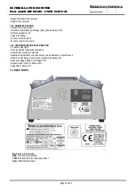
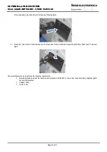
Defibrillator X has on the back a connector for receiving power from an external power source, as
seen in the following figure:
There you must connect the power cable reference 1846, to do this follow the following steps:
a)
Position the cable so that the connectors face each other and the male connector guides match the grooves of the female
connector, in the following figure you can see the female connector viewed from the front, where you can see the grooves for
the male connector guides:


