background image

DEFIBRILLATOR MONITOR  
Mod. 3850B-BIPHASIC - USER MANUAL


Page 20 of 63 


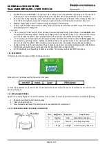
YELLOW LED: 

Off: Indicates no charge on the capacitor of the device. 

Flashing: Indicates that the device is in the process of storing energy. 

On: Indicates that the selected energy from the selector switch is ready to be discharged on the patient. 


ALARM INDICATORS 


HIGH PRIORITY alarm indicator: is indicated by a flashing red indicator, located in the upper left 

corner of the display. 


MEDIUM PRIORITY Alarm indicator: indicated by a yellow flashing indicator located in the upper 

left corner of the display 

LOW PRIORITY alarm indicator: indicated by a yellow continuous light indicator. 


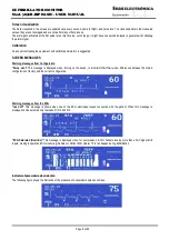
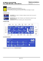
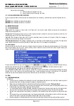
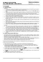
STANDARD SCREEN 


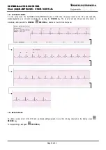
ECG SCREEN CASCADED 


To display the cascade ECG see section “CONFIGURATION MENU”


Summary of Contents for 3850

Page 1: ......

Page 2: ......

Page 3: ...DEFIBRILLATOR MONITOR Mod 3850B BIPHASIC USER MANUAL i DEFIBRILLATOR MONITOR Mod 3850B BIPHASIC USER MANUAL...

Page 4: ...r organization have access to this information including general safety information provided in section NOTES AND WARNINGS VERSION HISTORY This User Manual ref 16184 0903B MANUAL DE USO DESFIBRILADOR...

Page 5: ...NING ON THE DEVICE 22 2 3 TURN OFF THE EQUIPMENT 23 2 4 INTERNAL BATTERY 23 2 4 1 WARNING MESSAGES 23 2 4 2 DESCRIPTION 23 2 4 3 CHECKING THE BATTERY STATUS 24 2 5 EXTERNAL POWER SOURCE 24 3 USE MODE...

Page 6: ...G OF PAPER CHAMBER AND PRINTHEAD 44 4 2 5 OXIMETRY SENSOR CLEANING 44 4 3 DISINFECTION METHODS 44 4 4 STERILIZATION METHODS 44 4 5 PAPER REPLACEMENT 44 4 6 POWER SELECTOR 44 4 7 VERIFICATION OF ENERGY...

Page 7: ...ischarged Not suitable for explosive atmosphere Sound volume Connected to line or external 12Vdc Screen contrast Right Up Left Down Protective earth ground Warning High voltage Protect from rain Do no...

Page 8: ...of EN 60601 1 Cl 16 In any case the user should consult the manufacturer to ensure that the sum of leakage currents will not jeopardize patient safety The device is intended to be connected to Install...

Page 9: ...h the equipment or those accessories specially indicated for this equipment The use of accessories transducers and cables other than those specified with the exception of the transducers and cables so...

Page 10: ...lting in a false trigger and shocks the patient as well as cause burns at the shock time Never defibrillate a patient with the paddles wet Never defibrillate a patient on a wet surface More than 10 en...

Page 11: ...in contact with the patient if this is not possible remove the electrodes or metal parts before positioning the paddles During monitoring the ECG electrodes should be re positioned every 48 hours to...

Page 12: ...occurs Carefully route the patient cables extension cables oximetry sensors and or pacemaker electrodes to reduce the possibility of patient entanglement or strangulation CAUTIONS Only use the Oximet...

Page 13: ...thylene oxide Do not submerge any part of this equipment in water or other liquids or use abrasive cleaners Do not spray or spill liquids on the equipment or its accessories Do not allow any liquid en...

Page 14: ...rom Configuration Setup error This message is displayed when turning on the device is located that there are differences between the stored configuration of factory and the current configuration Warni...

Page 15: ...he energy test in the event of a successful outcome Failed test This message is displayed upon completion of the energy test in case of a failed result Warning messages from the oximeter Without senso...

Page 16: ...vice detects patient movement this message will be displayed Low perfusion In the presence of a weak signal or low perfusion will display the message Low perfusion SpO2 module error If there is no com...

Page 17: ...sage is displayed when the pacemaker is on and the selector switch moves from position MONITOR to the 2 Joules position or when the pacemaker is on and mode demand DEM and the patient cable is disconn...

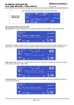
Page 18: ...ng messages BATTERY When the device s battery is fully discharged and the device is about to power down the screen will display messages Battery discharged and Powering down see figure below and in 12...

Page 19: ...mbination is detailed in the next table Ref Description 14634 DEFIBRILLATOR MONITOR WITH INTERNAL BATTERY 3850B BIPHASIC 14635 DEFIBRILLATOR MONITOR WITH INTERNAL BATTERY AND RECORDER 3850B BIPHASIC R...

Page 20: ...vasive electric pacing is contraindicated in the treatment of ventricular fibrillation it not respond to electrical stimulation and requires immediate defibrillation For that reason the patient arrhyt...

Page 21: ...porarily disconnected Keep the patient under close surveillance during periods of off alarm signals If the alarm signals are selected the visual alarm signal will continue to indicate the alarm condit...

Page 22: ...ction of pulse rate Alarm 1 3 5 TRANSCUTANEOUS PACER SECTION CF pacer output type Through external stimulation electrodes Pacer output connector polarized Selection and indication of pulses delivery m...

Page 23: ...or its parts or accessories in autoclave or ethylene oxide Do not submerge any part of this equipment in water or other liquids or use abrasive cleaners Do not spray or spill liquids on the equipment...

Page 24: ...DB9M G feas ELECTR NICA 520A OPTIONAL R R 17365 PULSE OXIMETER SENSOR PEDIATRIC DISPOSABLE DB9M G feas ELECTR NICA 520P OPTIONAL R 17366 PULSE OXIMETER SENSOR INFANT 3kg 20kg DISPOSABLE DB9M G 520I OP...

Page 25: ...lashes until it reaches the value of energy and then stays on Shock key Discharge the stored energy in the device over the patient through external paddles internal paddles or self adhesive patches Se...

Page 26: ...s ready to be discharged on the patient ALARM INDICATORS HIGH PRIORITY alarm indicator is indicated by a flashing red indicator located in the upper left corner of the display MEDIUM PRIORITY Alarm in...

Page 27: ...lies with the requirements of EN 60601 1 Cl 16 In any case the user should consult the manufacturer to ensure that the sum of leakage currents will not jeopardize patient safety The device is intended...

Page 28: ...the plug does not match the installation please contact our Customer Service for the provision of a suitable cable WARINING You must make sure that the AC outlet to which you will plug the device has...

Page 29: ...the equipment may still be operated via the internal battery If in addition the internal battery is discharged or damaged the unit will shut down It will remain off until the operator turns it back o...

Page 30: ...4 3 CHECKING THE BATTERY STATUS Procedure for check the battery status 1 Connect the device to AC line or 12Vdc external for 3 hours to achieve a full charge the internal battery 2 Unplug the device...

Page 31: ...e nut until it lock and make sure that the cable is firmly connected without the possibility of disconnect it see next figure The external power source must meet the following requirements Be medical...

Page 32: ...efibrillator will discharged the energy internally automatically By default the automatic disarm time is 60 seconds For more information on how to configure the automatic disarm time refer to SETUP ME...

Page 33: ...rts exposed skin head arms and legs with metallic objects such as parts of the bed that might generate non desired paths for the defibrillation current WARNING Rescuers performing chest compressions d...

Page 34: ...will light indicating that it is in synchronous mode and also be displayed on the display the text SYNC Place the paddles on the patient see section EXTERNAL PADDLE POSITIONING and make sure no one is...

Page 35: ...the device in MONITOR mode Once you enter the menu release the key and use the keys for select YES or NO and keys to select another menu option If the ECG display mode is cascade you can t enable the...

Page 36: ...r for electrosurgery since the equipment is electrically isolated although the paddles should not be positioned close to or on the electrodes or metal parts in contact with the patient if this is not...

Page 37: ...oose DI DII DIII or paddles onscreen I II III and PAD and with a 5 wire patient ECG cable DI DII DIII aVL aVR aVF C or paddles onscreen I II III aVL aVR aVF C and PAD When the patient ECG cable is not...

Page 38: ...e field Press the key or key to increase or decrease the date Repeat the above steps to set the time 3 3 4 7 Volume To adjust the QRS beep volume scroll with keys and move the cursor to the volume ico...

Page 39: ...lethysmographic curve will start immediately by pressing the CHARGE key The recorder will stop 20 seconds after shock or immediately after press button DISARM or RECORD key located on the left of the...

Page 40: ...Mod 3850B BIPHASIC USER MANUAL Page 34 of 63 One curve registered Two curves registered 3 4 3 Indicator of pacemaker spike detection The following figure shows the indication of the presence of pacema...

Page 41: ...cessary to disconnect the ECG electrodes Pacemaker electrodes and or Oximetry sensor for electrosurgery since the equipment is electrically isolated although the paddles should not be positioned close...

Page 42: ...bloodstream such as methylene blue indocyanine green indigo carmine and fluorescent can affect the accuracy of SpO2 reading Any condition that may reduce the blood flow like the usage of cuff to meas...

Page 43: ...does not stretch or tighten it If the tape is too tight can cause inaccurate readings and blisters on the skin of the patient the blisters are caused by lack of skin breath not by heat Replace the Ox...

Page 44: ...ed while the oximeter detects pulse Not found If pulse is not found after a long period of time the message Not found will be displayed Movement Once connected the Oximetry sensor and if the device de...

Page 45: ...ter replace the sensor for a new one If it still does not meet specifications send the device to Technical Service The following table shows the values of measurements and tolerances Oximeter FINAL TE...

Page 46: ...xygen saturation of arterial blood can be calculated by measuring light absorption during pulsation The pulsation control system provides a pulse waveform and a pulse signal For the measurement the wa...

Page 47: ...re below and an auditory signal see AUDITORY ALARM SIGNALS OF MEDIUM PRIORITY Finally a low priority alarm is indicated by a yellow continuous light indicator located in the upper left corner of the d...

Page 48: ...nt will shut down Burst 10 pulses every 2 5s High DEFIBRILLATION High priority alarm with the exception that the auditory signal is not a high priority signal but is a continuous beep signal Error in...

Page 49: ...ut authorization from the manufacturer WARNING If you modify this equipment must perform appropriate tests and inspections to ensure continued safe use of equipment ATTENTION It suggests an annual con...

Page 50: ...ve or ethylene oxide Do not submerge any part of this equipment in water or other liquids or use abrasive cleaners Do not spray or spill liquids on the equipment or its accessories Do not allow any li...

Page 51: ...gy test ensures that the equipment is able to deliver energy on paddles or determine that due to a fault does not allow delivery of energy on paddles If the test failed contact the feas ELECTR NICA s...

Page 52: ...re patient ECG cable selecting in the simulator the following values normal ECG amplitude 1mV frequency 60 1 min Then set alarm limits as follows Lower Alarm Limit 30 1 min Upper Alarm Limit 120 1 min...

Page 53: ...battery is indicated on the screen and therefore requires that the device is on MONITOR or energy selection and operating from the internal battery disconnected from AC line or external 12Vdc If the...

Page 54: ...S beep The motherboard is faulty Send the equipment to our Customer Service for repair No audible alarm signal The key Alarm silence is activated Pres the key Alarm silence again The alarms are disabl...

Page 55: ...the signal is restored automatically Faulty motherboard Send the equipment to our Customer Service for repair Selected ECG curve isn t viewed and message ECG Saturated appear There is a very powerful...

Page 56: ...e it If this solves the problem send the sensor for repair else send the sensor and equipment to our Customer Service for repair The message Low Perfusion appears Indicates that where the sensor is pl...

Page 57: ...240Vac 50Hz 60Hz Electrical Specifications Power supply 90Vac 240Vac automatic selection and notch filter 50Hz or 60Hz factory selectable External Power 12Vdc Internal Power Supply Battery 12V 3500mA...

Page 58: ...x 2 30KV Inductance 23mHy Internal resistance 8 Maximum charge energy 200 Joules Waveform Biphasic Charge time to 200J Nominal Line 6s 90 of nominal line 7s Full battery 6s After 15 shocks of 200J 6s...

Page 59: ...F Notch Filter 50Hz or 60Hz factory Determined Indication of QRS QRS Beep and image Alarm Silence keyboard 2 minutes Lead Selection Keyboard DI DII DIII and PAD Paddles or DI DII DIII aVR aVF aVL prec...

Page 60: ...A1 Ventricular Bigeminy Measured and indicated frequency on display after 20s of establishment 80 1 min 5 1 min Signal A2 Slow alternating Ventricular Bigeminy Measured and indicated frequency on dis...

Page 61: ...Vpp 206 1 min the time is the same For different amplitudes of B1 and B2 half and twice the alarm time is still the same Rejection capacity of high T wave Maximum T wave amplitude rejected 1 2 times t...

Page 62: ...defined Neonatal accuracy 3 de 70 a 100 70 is not defined Movement accuracy 3 de 70 a 100 Resolution 1 The specified accuracy is the root mean square RMS difference between the measured values and re...

Page 63: ...0 to 10 of pulse tf 20ms If the physiological alarm condition is maintained the pulse burst is repeated every 7 5s as shown in the next figure The auditory alarm signal of a technical alarm condition...

Page 64: ...of 1000Hz The detail of the pulse shown in the next figure Rise time from 10 to 90 of pulse tr 20ms Effective duration time of pulse td 200ms Fall time from 90 to 10 of pulse tf 20ms The pulse of the...

Page 65: ...ms Effective duration time of pulse td 100ms Fall time from 90 to 10 of pulse tf 20ms The sound pressure is adjusted from the volume adjustment function 6 10 CONFIRMATION SOUND OF KEY PRESSED Pressing...

Page 66: ...etic environment guidance Electrostatic discharge ESD 6kV by contact 6kV by contact Floors should be wood concrete or ceramic tile If floors are covered with synthetic material the relative humidity s...

Page 67: ...may not apply in all situations Electromagnetic propagation is affected by absorption and reflection from structures objects and people a The ISM industrial scientific and medical bands between 150kHz...

Page 68: ...x 0 01 0 117 0 12 0 12 0 23 0 1 0 37 0 379 0 379 0 727 1 1 17 1 2 1 2 2 3 10 3 7 3 79 3 79 7 27 100 11 7 12 12 23 For transmitters rated at a maximum output power not listed above the recommended sep...

Page 69: ...tions not prescribed by the User manual 5 Warranty void if it becomes apparent that a Amendments or deletions in the certificate data or purchase invoice b Lack of original purchase invoice or lack of...

Page 70: ......

Page 71: ......

Page 72: ......

Reviews: