background image

Part No. SCAZ042891 1.3.4

37

E&OE

Operating Instructions Scarab M6

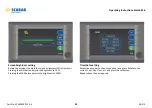
CAN error screen

Identifies location of system errors.
Highlighted in red when active.

Driver fault codes

Entering a Node screen allows Pin-Contact view.
Pin numbers with an active fault are highlighted in RED.

= Open Circuit
= Short

Summary of Contents for SCARAB M6

Page 1: ...SKID MOUNTED SWEEPING MACHINES Technical operating and basic maintenance instructions This document contains important Health and Safety advice and must remain with the Machine at all times M6 ...

Page 2: ...rientation determined by driving side 6 Central brush Wide sweep 7 Rear door open close ram 8 HP hose reel option orientation determined by driving side 1 2 3 4 8 5 6 7 9 9 LP and or HP spraybar 10 Hydraulic valve block hydraulic cooler access door 11 Auxiliary hand pump 12 Side brush assembly 13 Suction nozzle assembly 14 Rear loading hatch access ladder option orientation determined by driving s...

Page 3: ...nsure that the information it contains is correct at the time of publication Due to a policy of continuous development however the Company reserves the right to alter the specification and to supply when so altered without reference to illustrations and descriptions in this manual Scarab Sweepers Limited Pattenden Lane Marden Kent TN12 9QD England T 44 0 1622 831 006 F 44 0 1622 832 417 E scarab s...

Page 4: ...RANSMISSION COULD RESULT IF THE MACHINE IS TOWED WHILE THE GEARBOX IS ENGAGED If towing is necessary it is imperative that the prop shaft is disengaged from the differential or that the rear wheels are clear of the ground before making any attempt to tow the vehicle IDENTIFICATION PLATES The SERIAL NUMBER PLATE is located at the base of the hydaulics enclosure on the lefthand side of the skid unit...

Page 5: ... TIPPING 14 Rear Door Operation 15 Rear Door Prop 15 USING THE AUXILIARY HAND PUMP 16 REAR MOUNTED WANDER HOSE 17 Para Title Page USING THE DUST SUPPRESSION SYSTEM 18 Filling the water tank 18 Using the low pressure water system 18 USING THE HIGH PRESSURE WATER SYSTEM OPTION 19 Retractable hose 19 CLEARING A BLOCKAGE IN THE SUCTION PATH 20 RECOMMENDED OPERATOR S ROUTINE MAINTENANCE 22 KEY MAINTENA...

Page 6: ...WATER CAN BE HAZARDOUS ALWAYS WEAR SUITABLE FACE PROTECTION WHEN OPERATING THE HIGH PRESSURE WATER PUMP AND WHEN USING THE LANCE DO NOT DIRECT THE WATER JET AT OTHER PERSONS BEWARE OF ELECTRICAL INSTALLATIONS ON PUBLIC BUILDINGS LAMP POSTS etc AND ALWAYS EXERCISE EXTREME CAUTION IN PUBLIC PLACES THE DRIVER S SEAT SHOULD BE CORRECTLY ADJUSTED AS TO GIVE A GOOD POSTURE WHEN DRIVING THE MIRRORS SHOUL...

Page 7: ...jects e g broken glass discarded hypodermic syringes while operating or working on the Machine Exposure to various infectious diseases e g Legionnaire s Weil s Hepatitis Tetanus while operating or working on the Machine SAFETY PRECAUTIONS When using external equipment such as the high pressure water lance or when dealing with potentially hazardous situations while sweeping e g unblocking a suction...

Page 8: ...ut the fan blades on its way back to the environment behind you Operators should be trained in the following elements Health safety observations notices Transit driving In cab external controls Hopper safety cab prop use Brush setting Nozzle flap adjustment Correct sweeping operations Low high pressure water systems Load discharge tipping Daily weekly maintenance schedules End of day cleaning ie s...

Page 9: ...p ensure it is correctly positioned in the locating slot Ensure the prop is completely unlatched when the hopper is in the raised position Never work under a partially raised hopper or if the hopper Pull lever as shown until the hopper prop is correctly latched before lowering the hopper HOPPER SAFETY PROP prop is latched ...

Page 10: ... Each switch illuminates a function related symbol on the LCD monitor only installed equipment will be displayed Each symbol is greyed out until its switch is activated When a switch is activated the appropriate symbol will illuminate according to system status as illustrated Not selected Pre selected Water pre selected Brush water pre selected Equipment working Not selected Pre selected Equipment...

Page 11: ...brush LEFT RIGHT SUCTION NOZZLE RAISE LOWER Press to lower the suction nozzle WIDESWEEP BRUSH Press to start the widesweep brush LEFT RIGHT WORK LIGHT Press to turn ON LEFT RIGHT SIDE BRUSH NOZZLE WATER Press to start the side brush and suction nozzle dust suppression WIDESWEEP WATER Press to start the dust suppression spray for the widesweep brush INCREASE REDUCE AUXILIARY ENGINE SPEED Press and ...

Page 12: ...started Repeat to over ride with a new configuration MULTI FUNCTION LEVER ON deploys all selected sweeping equipment To stop and raise all sweeping equipment return the lever to the OFF position In the ON position the lever can be used to control the side brushe s and suction nozzle s These additional positions i e Left Right and Back return to the central position when released The brush and nozz...

Page 13: ...gs HOPPER RAISE Press and hold down to raise the hopper The hopper prop must always be in the deployed position when the hopper is in the raised position Failure to do could result in serious injury HOPPER LOWER Press and hold down to lower the hopper REAR DOOR OPEN Press and hold down until the door is Fully open at approximately 90 to the rear face of the hopper Ensure that the suction fan is OF...

Page 14: ...ng buzzer For warnings identified by stop and investigate the cause The accompanying illustration shows the range of information alert symbols that can be displayed however it should be noted that warning symbols only illuminate when a specific condition occurs HIGH PRESSURE WATER ON NO WATER ASIGN NODE SERVICE REMINDER HYDRAULIC OIL TEMPERATURE WARNING FAULT ACTIVE HOPPER RAISED LOW WATER LEVEL D...

Page 15: ...sh es AIR PRESSURE GAUGE Indicates the amount of pressure being applied to the brush es BRUSH PRESSURE SWITCH This switch works in conjunction with the side brush down switch on the main control panel These functions are only effective while the relevant brushes are fully deployed PRESSURE GAUGE PRESSURE REGULATOR IN CAB CONTROLS WIDESWEEP CONTROLS Typical Arrangement Positions will vary according...

Page 16: ... following events occur The CANbus system checks that all control nodes are present and functioning correctly and the LCD Monitor turns on briefly displaying the Scarab logo for approx 12 seconds before changing to display a basic truck graphic as well as the suction fan and auxiliary engine speed scales If a system error is detected at this stage the Fault Active symbol will illuminate To identif...

Page 17: ...and all water spray jets will stop this will also occur automatically as soon as REVERSE is engaged reverting to the original configuration as soon as REVERSE is disengaged 5 Operate the multi function switch to swing the side brushes OUT and the Nozzle Tilt switches auxiliary control panel as required to suit the sweeping conditions The multi function switch can also be used to control nozzle til...

Page 18: ...tion All active sweep systems will stop and retract If the Multi Function Switch is not returned to the OFF position at this point the sweeping equipment will not function upon any subsequent resumption of Sweep Mode until it has been first moved to the OFF position and then returned to the ON position 3 Allow the auxiliary engine to idle for approximately two minutes and then press the System Sta...

Page 19: ...ve the hopper prop lever as illustrated to engage with the prop latching assembly Lower the hopper fully Before closing the door ensure that the door seal and mating faces on the hopper are free from any foreign matter that might damage the seal or adversely affect the sealing function The rear door will not close via the remote control unless the hopper is in the fully down position as determined...

Page 20: ...e rear door safety prop if working around or under the rear door 8 Ensure that the rear door seal and its mating surfaces on the hopper are free from any foreign matter that might damage the seal or adversely affect the sealing function 9 Remove and stow the rear door safety prop 10 Close rear door by pressing and holding the auxiliary engine speed will raise to 1500rpm the auto blanking flaps wil...

Page 21: ...e remote control and hold while operating the pump handle If electrical power is unavailable proceed as follows 5 Depress the locking button 1 and push pull the control ring 2 to operate either the hopper or rear door Refer to illustration 6 Operate the pump handle 3 The hopper prop must always be in the deployed position when working beneath a raised hopper failure to do so could result in seriou...

Page 22: ... Failure to do so will result in poor suction when sweeping For situations requiring maximum suction power ie when removing stubborn objects etc select fan boost To visually inspect the hopper interior a hatch and ladder are installed in the rear door Lower the ladder to gain access The machine must be off ignition key removed and parking brake on Alwaysexerciseextreme cautionwhen opening thehatch...

Page 23: ...es suction tube s and widesweep brush To operate any of these functions the relevant button s on the main panel must be selected when in sweep mode A shut off valve is positioned between the pump and tank and must be open when the system is in use 3 The side brush es are fitted with shut off valves 4 It is vital that the water system is drained totally if the air temperature is expected to fall to...

Page 24: ...ol panel and open the appropriate valve s for the function s required Retractable hose The hand lance 2 is attached to a 13 metre long rubber hose fitted to a hose reel 3 When extending the hose a ratchet mechanism allows the reel to lock in place Further extending past the ratchet allows the reel to retract The position of the hose reel and hand lance is determined by the machine specification Th...

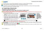
Page 25: ...em keeping such activities to the absolute minimum Only when all of the foregoing points have been complied with should the clearance procedure commence If it is not possible to comply with these conditions you are advised to consult your supervisor before acting The procedure for clearing the suction path is as follows 1 Raise the hopper ensuring the safety prop is deployed to gain access to the ...

Page 26: ...Part No SCAZ042891 1 3 4 26 E OE Operating Instructions Scarab M6 AREA MOST LIKELY TO SUFFER A BLOCKAGE ...

Page 27: ...d nozzle wheel 12 Remove clean the L P and H P water filter elements 13 Clean the suction fan thoroughly using the scraper provided and high pressure water See Page 28 14 Conduct a thorough inspection of the fan assembly to verify its condition Report any defects See Page 28 15 Grease hopper ram Top and bottom 16 Visually check entire machine for wear damage 17 Check wiring and hoses for security ...

Page 28: ...enabling you to reach the area above the rear door 2 With the fan stationary remove the outer and inner inspection covers from the hopper to expose the fan 3 Using the special scraper thoroughly clean all parts of the fan A steam cleaner or high pressure water from a remote source will greatly assist in cleaning severely contaminated fans 4 Refit the inspection covers and open the rear door Lower ...

Page 29: ...lates Ensure they are free from contamination that may cause them to become slippery Always wear suitable footwear with clean and dry soles Ensure that the Machine is on a flat and level surface with the auxiliary engine stopped for a suitable period to allow the oil to return to the sump Engine oil level 1 Remove the dipstick 1 from the holder 2 Wipe clean with a lint free cloth 3 Replace in it h...

Page 30: ...e the hopper in accordance with the instructions detailed on Page 19 Ensure that the Machine is on a flat and level surface with the auxiliary engine stopped for a suitable period to allow the engine to cool Topping up 1 Remove the filler cap from the coolant expansion tank 1 2 Run the engine for several minutes 3 Stop engine and check coolant level Top up to the appropriate level using the correc...

Page 31: ...liary engine stopped for a suitable period to allow the engine to cool Topping up 1 Open the right hand engine gantry door to gain access to the hydraulic tank 2 Using the appropriate size spanner remove the filler cap 1 3 Top up with HPL 32 or an equivalent hydraulic oil to the appropriate level Pay particular attention the hopper orientation as indicated on the level label when filling Hydraulic...

Page 32: ...uce excellent results in most conditions Experience will determine if other settings are better suited to specific conditions 1 Vehicle stopped handbrake ON sweep mode ON activate the desired brush es in their working positions 2 Switch OFF ignition and remove the key Before proceeding ensure people and objects are clear of the brush area 3 Locate the appropriate valve s in the pneumatic cabinet a...

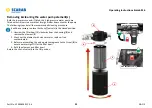
Page 33: ...nded cleaning procedure It will be necessary to place the shut off valve s in the closed position 1 Unscrew the filter bowl 1 clockwise from the housing 2 and remove the element 3 2 Wash out the element with clean water or replace if too contaminated 3 Before re assembling the unit apply some grease to the O seal 4 to ensure a water tight fit for the filter bowl 4 Refit the element and filter bowl...

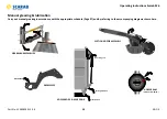
Page 34: ...Carry out manual greasing in accordance with the appropriate schedule Page 27 and by referring to the accompanying diagrams shown here SUCTION NOZZLE ASSEMBLY HOPPER RAM Viewed from Below SIDE BRUSH ASSEMBLIES WIDESWEEP BOTH SIDES Door Hinge x3 Pivot Rod x2 Locking Clamp x3 HOPPER BODY REAR DOOR ...

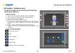
Page 35: ...ted 3 Hours Press to view hours logged 4 Return Press to return to previous screen 5 Encoder Turn to highlight required option press to enter Used in all screen modes Press to display side tabs from the sweeping mode screen 6 Camera Press to enable in forward drive rear view only 7 Hopper raise lower and rear door open close warning buzzer Press to disable Screen menu description Driver s fault co...

Page 36: ...6 E OE Operating Instructions Scarab M6 Hours worked Displays the working time of various functions Service Hours only display when activated Driver fault codes Highlight either the CAN or desired Node Press the encoder to enter ...

Page 37: ...structions Scarab M6 CAN error screen Identifies location of system errors Highlighted in red when active Driver fault codes Entering a Node screen allows Pin Contact view Pin numbers with an active fault are highlighted in RED Open Circuit Short ...

Page 38: ... the following current conditions Engine Speed Battery Voltage Coolant Temperature Turbo Boost Pressure Turbo Air Pressure Fuel Pressure Barometric Pressure Fuel Temperature Engine Load Screen Settings Highlight the desired panel and press the encoder to enter the setting screen ...

Page 39: ...o adjust the screen brightness 2 increments Pressing the MIN button adjusts the brightness to 10 Pressing the MAX button adjusts the brightness to 100 Time date setting Rotate the encoder to the desired panel and press Rotate to the correct Year Day Hour etc and press the set button Repeat above step as required ...

Page 40: ...ctivated NOTE This function allows rear viewing when the vehicle is in forward drive When reversing the screen activates automatically Information Displays current Node program version Press button 1 to access the PDF viewing screen Follow the on screen directions Only to be used when vehicle is stationary and auxiliary engine is off NOTE On exiting PDF viewer ignition must be cycled ...

Page 41: ...utton checks Highlight the appropriate panel and press the controller Main control panel button check Press the appropriate button on the main control panel As each button is pressed the corresponding graphic will illuminate A beep will sound if the function is fitted ...

Page 42: ...Part No SCAZ042891 1 3 4 42 E OE Operating Instructions Scarab M6 Auxiliary control panel button check Use the main control panel instructions to test buttons and joystick ...

Page 43: ...Part No SCAZ042891 1 3 4 43 E OE Operating Instructions Scarab M6 Operator s notes ...

Page 44: ...Part No SCAZ042891 1 3 4 44 E OE Operating Instructions Scarab M6 Operator s notes ...

Page 45: ...Scarab M6 Operating Instructions Part No SCAZ042891 1 3 4 47 E OE ...

Page 46: ...42891 1 3 4 E OE Scarab Sweepers Limited Pattenden Lane Marden Kent TN12 9QD Telephone 01622 831 006 Fax 01622 832 417 International 44 0 1622 831 006 International 44 0 1622 832 417 e mail scarab scarab sweepers com Website www scarab sweepers com ...

Reviews: