


Machine description
4812163901_A.pdf
2019-09-23
Location - decals, CALIFORNIA
Proposition 65
1
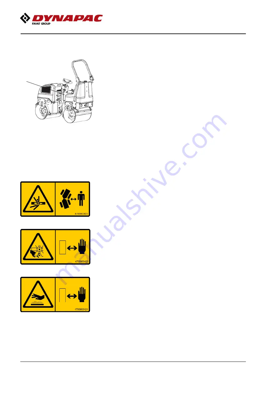
Fig. Location
1.
Warning, CALIFORNIA
Proposition 65
4812130471
1.
Warning, CALIFORNIA
Proposition 65
4812130471
Safety decals
Always make sure that all safety decals are completely
legible, and remove dirt or order new decals if they
have become illegible. Use the part number specified
on each decal.
4700903422
Warning - Crush zone, articulation/drum.
Maintain a safe distance from the crush zone.
(Two crush zones on machines fitted with pivotal steering)
4700903423
Warning - Rotating engine components.
Keep your hands at a safe distance.
4700903424
Warning - Hot surfaces in the engine compartment.
Keep your hands at a safe distance.
26
Summary of Contents for Dynapac CC900G
Page 2: ......
Page 12: ...Introduction 4812163901_A pdf 2019 09 23 4 ...
Page 20: ...Special instructions 4812163901_A pdf 2019 09 23 12 ...
Page 28: ...Technical specifications 4812163901_A pdf 2019 09 23 20 ...
Page 40: ...Machine description 4812163901_A pdf 2019 09 23 32 ...
Page 48: ...Operation 4812163901_A pdf 2019 09 23 40 ...
Page 56: ...Operating instructions Summary 4812163901_A pdf 2019 09 23 48 ...
Page 62: ...Maintenance Lubricants and symbols 4812163901_A pdf 2019 09 23 54 ...
Page 78: ...Maintenance 100h 4812163901_A pdf 2019 09 23 70 ...
Page 86: ...Maintenance 500h 4812163901_A pdf 2019 09 23 78 ...
Page 94: ...Maintenance 1000h 4812163901_A pdf 2019 09 23 86 ...
Page 103: ......
Page 104: ...Dynapac Compaction Equipment AB Box 504 SE 371 23 Karlskrona Sweden www dynapac com ...


