Fayat Group DYNAPAC CA1300 D Instruction Manual Download Page 70

Operation

4812165001.pdf

2023-05-26

Operator position

3

1

3

2

4

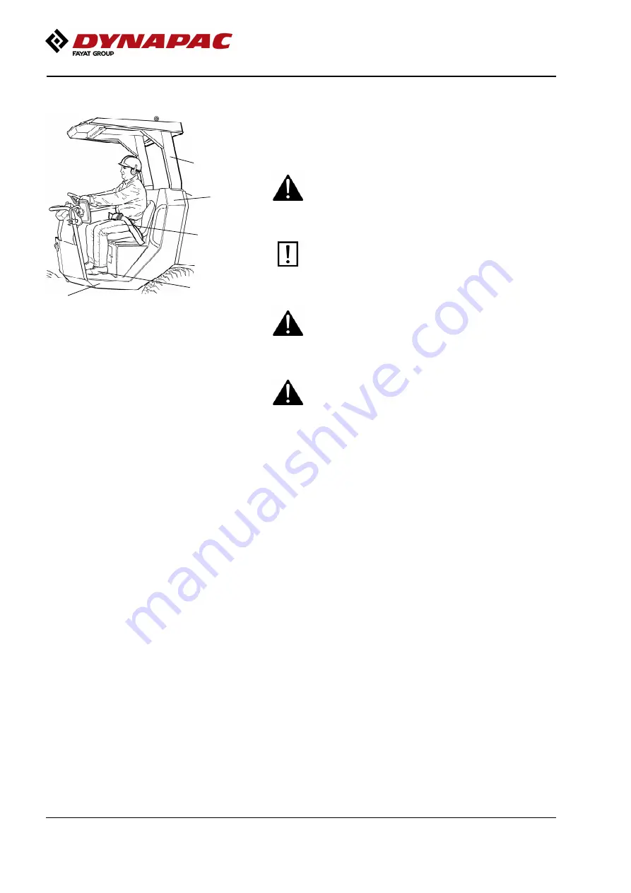
Fig. Operator's station
 1. Seat belt
 2. ROPS structure
 3. Rubber element
 4. Anti-slip

If a ROPS (2) (Roll Over Protective Structure) or
a cab is fitted to the roller, always wear the seat belt
(1) provided and wear a protective helmet.

Replace the seat belt (1) if it shows signs of
wear or has been subjected to high levels
of force.

Replace the seat belt (1) if it shows signs of
wear or has been subjected to high levels
of force.

Check that rubber elements (3) on the platform
are intact. Worn elements will impair comfort.

Check that rubber elements (3) on the platform
are intact. Worn elements will impair comfort.

Ensure that the anti-slip (4) on the platform is in
good condition. Replace where anti-slip friction
is poor.

Ensure that the anti-slip (4) on the platform is in
good condition. Replace where anti-slip friction
is poor.

If the machine is fitted with a cab, make sure
that the door is closed when in motion.

If the machine is fitted with a cab, make sure
that the door is closed when in motion.

52

Summary of Contents for DYNAPAC CA1300 D

Page 1: ...atory roller CA1300 D PD CA1300 D PD Engine Engine Yanmar 4TNV98CT Tier 4f Stage V Yanmar 4TNV98CT Tier 4f Stage V Serial number Serial number 10000203xxA036288 10000203xxA036288 Translation of original instruction Translation of original instruction Reservation for changes Reservation for changes Printed in Sweden Printed in Sweden ...

Page 2: ......

Page 3: ...dges 7 Work driving 8 Safety Optional 9 Strike off blade 9 Special instructions 11 Standard lubricants and other recommended oils and fluids 11 Higher ambient temperatures above 40 C 104 F 11 Temperatures 11 High pressure cleaning 12 Fire fighting 12 Fire extinguisher 13 Roll Over Protective Structure ROPS 13 Battery handling 13 Jump starting 14 Technical specifications 15 Noise level 15 Vibration...

Page 4: ...chine description 23 Diesel engine 23 Electrical system 23 Propulsion system Transmission 23 Brake system 23 Steering system 24 Vibration system 24 Cab 24 Emergency exit 24 Seat 24 FOPS and ROPS 24 Identification 25 Product and component plates 25 Product identification number on the frame 25 Machine plate 26 Explanation of 17PIN serial number 26 Engine plates 27 Decals 28 Location decals 28 Locat...

Page 5: ...Operation 41 Using the cab controls 44 Defroster 44 Heat 44 Electrical system 45 Fuses 45 Fuses in cab 46 Main fuses 46 Relays on machine 47 Operation 49 Before starting 49 Master switch Switching on 49 Operator s seat Adjusting 50 Driver seat Equipment status Adjustment 50 Parking brake 51 Interlock 51 Operator position 52 Instruments and lamps Checking 53 View 53 Working lights Adjustment 54 Rea...

Page 6: ... stop Parking brake Check 59 Regeneration of DPF filter 59 Tampering of DPF 61 High ash levels 62 Vibration 62 Vibration On Off 62 Braking 63 Service brake 63 Normal braking 63 63 Reserve brake 64 Emergency stop 64 Switching off 65 Parking 65 Chocking the drums 65 Master switch 66 Long term parking 67 Engine 67 Battery 67 Air cleaner exhaust pipe 67 Fuel tank 67 Hydraulic reservoir 67 Steering cyl...

Page 7: ...xle brake 71 Brake disengagement 71 Releasing the drum brake 72 Drum motor brake 72 Towing 73 Transport 73 Securing 74 Operating instructions Summary 79 Preventive maintenance 81 Acceptance and delivery inspection 81 Warranty 81 Maintenance Lubricants and symbols 83 Maintenance symbols 85 Maintenance Maintenance schedule 87 Service and maintenance points 87 General 88 Every 10 hours of operation D...

Page 8: ... 98 Service Checklist 99 Maintenance 10h 101 Scrapers Check adjustment 101 Scrapers Pad drum 102 Air circulation Check 102 Coolant level Check 103 Windscreen washer fluid Checking and filling 104 Diesel engine Check oil level 104 Fuel tank Filling 105 Hydraulic reservoir Check fluid level 105 Air filter indicator Resetting 105 Air cleaner Check Replacement of main filter 106 Backup filter Change 1...

Page 9: ...ecking the belt tension 119 Rubber elements and fastening screws Check 119 Bolted joints Checking tightening torque 120 Fuel tank Cleaning 120 Fuel tank Draining Equipment status 121 Maintenance measures 500 2500 3500 4500 5500 6500 9500h 123 Battery Check condition 123 Rear axle differential Check oil level 124 Rear axle pinion housing Checking the oil level 124 Rear axle planetary gears Check oi...

Page 10: ...5 Cab hinges Lubrication 136 Air conditioning Optional Fresh air filter Change 136 Air cleaner Check Replacement of main filter 136 Air filter indicator Resetting 137 Backup filter Change 137 Compressor belt Adjustment 137 Air conditioning Optional Check 138 Automatic Climate Control Optional Overhaul 138 Maintenance 1000h 139 Battery Check condition 139 Rear axle differential Oil change 140 Rear ...

Page 11: ...152 Forward Reverse controls and joints Check and lubrication 154 Accessing the machine fitted with ROPS 154 Access on machine with cab 154 Hood hinges Lubrication 155 Cab hinges Lubrication 156 Air conditioning Optional Fresh air filter Change 156 Air cleaner Check Replacement of main filter 156 Air filter indicator Resetting 157 Backup filter Change 157 Compressor belt Adjustment 157 Air conditi...

Page 12: ...66 The engine fuel pre filter replacement cleaning 167 The engine fuel filter replacement cleaning 168 Diesel engine Oil and Filter change 169 Changing the engine oil 169 Changing the oil filter 169 Forward Reverse controls and joints Check and lubrication 171 Accessing the machine fitted with ROPS 171 Access on machine with cab 171 Hood hinges Lubrication 172 Cab hinges Lubrication 173 Air condit...

Page 13: ...stening screws Check 182 Bolted joints Checking tightening torque 183 Fuel tank Cleaning 183 Fuel tank Draining Equipment status 184 Hydraulic reservoir Draining 184 Hydraulic filter Replacement 185 Pre fuel filter Draining 187 The engine fuel pre filter replacement cleaning 188 The engine fuel filter replacement cleaning 189 Diesel engine Oil and Filter change 190 Changing the engine oil 190 Chan...

Page 14: ...ance 3000 5000 7000 h 199 Battery Check condition 199 Rear axle differential Oil change 200 Rear axle pinion housing Oil change 200 Rear axle planetary gear Oil change 201 Drum Checking the oil level 202 Coolers Checking Cleaning 203 Replacing belts Checking the belt tension 204 Rubber elements and fastening screws Check 204 Bolted joints Checking tightening torque 205 Fuel tank Cleaning 205 Fuel ...

Page 15: ...ement of main filter 216 Air filter indicator Resetting 217 Backup filter Change 217 Compressor belt Adjustment 217 Automatic Climate Control Optional Overhaul 218 Air conditioning Optional Check 218 Inspect ECU related sensors and actuators 218 Inspect turbocharger 219 Inspect DPF and related sensors 219 Inspect and test intake throttle valve 219 Check and clean injector 219 Maintenance 6000h 221...

Page 16: ...fuel filter replacement cleaning 234 Diesel engine Oil and Filter change 235 Changing the engine oil 235 Changing the oil filter 235 Forward Reverse controls and joints Check and lubrication 237 Accessing the machine fitted with ROPS 237 Access on machine with cab 237 Hood hinges Lubrication 238 Cab hinges Lubrication 239 Air conditioning Optional Fresh air filter Change 239 Air cleaner Check Repl...

Page 17: ...Check 248 Bolted joints Checking tightening torque 249 Air conditioning Optional Check 249 Fuel tank Cleaning 250 Fuel tank Draining Equipment status 250 Hydraulic reservoir Draining 251 Hydraulic filter Replacement 251 Pre fuel filter Draining 253 The engine fuel pre filter replacement cleaning 254 The engine fuel filter replacement cleaning 255 Diesel engine Oil and Filter change 256 Changing th...

Page 18: ...hange 261 Compressor belt Adjustment 261 Automatic Climate Control Optional Overhaul 262 Check and adjust intake exhaust valve clearance 262 Replacing DPF 262 Maintenance every 24th month Every other year 263 Cooling water system Check 263 Coolant Change 264 Replace via coolant hose 264 Replace via crankcase 264 Check Air intake hose 265 Replacing belts Checking the belt tension 265 ...

Page 19: ...l hazardous situation procedure which if not avoided could result in death or serious injury CAUTION Indicates potential hazardous situation procedure which if not avoided could result in minor or moderate injury damage to the machine or property CAUTION Indicates potential hazardous situation procedure which if not avoided could result in minor or moderate injury damage to the machine or property...

Page 20: ...nance Read the entire manual before starting the machine and before carrying out any maintenance Replace immediately the instruction manuals if lost damaged or unreadable Replace immediately the instruction manuals if lost damaged or unreadable Only the operator is allowed to be on the roller Only the operator is allowed to be on the roller Ensure good ventilation extraction of air by fan where th...

Page 21: ...iodic maintenance where maintenance after every 10 and 50 hours of operation can be performed by the machine operator Other maintenance intervals must be carried out by accredited Dynapac service personnel Additional instructions for the engine can be found in the manufacturer s engine manual Additional instructions for the engine can be found in the manufacturer s engine manual Specific maintenan...

Page 22: ...Introduction 4812165001 pdf 2023 05 26 4 ...

Page 23: ...have full bearing strength or the edge is close to a slope Avoid operating close to edges and ditches and the like as well as on poor ground conditions that jeopardizes the bearing strength and capacity to support the roller Never operate with the drum outside the edge the substrate might not have full bearing strength or the edge is close to a slope Avoid operating close to edges and ditches and ...

Page 24: ...de after written approval has been given by Dynapac Avoid using the roller before the hydraulic fluid has reached its normal working temperature Braking distances can be longer than normal when the fluid is cold Avoid using the roller before the hydraulic fluid has reached its normal working temperature Braking distances can be longer than normal when the fluid is cold For your own protection alwa...

Page 25: ...nd operate the machine only when the person is fully visible or has given a clear indication of where he or she is Avoid driving across a slope Drive straight up and down sloping ground Avoid driving across a slope Drive straight up and down sloping ground Driving near edges Never operate with the drum outside the edge the substrate might not have full bearing strength or the edge is close to a sl...

Page 26: ...ed cab and seat belt usage Avoid operating close to edges and ditches and the like as well as on poor ground conditions that jeopardizes the bearing strength and capacity to support the roller Pay attention to potential obstacles above the machine such as overhead cables and the branches of trees etc Pay particular attention to the stability of the substrate when compacting close to edges and hole...

Page 27: ...he area of operation while the machine is in use The operator must make sure that nobody is in the area of operation while the machine is in use The strike off blade must be retracted to the transport position at the end of each working period The strike off blade must be retracted to the transport position at the end of each working period 9 ...

Page 28: ...Safety Optional 4812165001 pdf 2023 05 26 10 ...

Page 29: ...is 35 C 95 F Higher ambient temperatures above 40 C 104 F For operation of the machine at higher ambient temperatures however maximum 50 C 122 F the following recommendations apply The diesel engine and hydraulic system can be run at this temperature using normal oil but in other components that use transmission oil Shell Spirax S3 AX85W 140 API GL 5 or equivalent must be used Other components tha...

Page 30: ...ment Protective goggles Protective goggles Protective gloves Protective gloves Ear protectors Ear protectors Detergent that can destroy electrical parts or which is conductive must not be used Detergent that can destroy electrical parts or which is conductive must not be used Never aim the water jet directly at the fuel tank cap or into exhaust pipe This is particularly important when using a high...

Page 31: ...out any welding or drilling operations of any kind on the Roll Over Protective Structure ROPS Never attempt to repair a damaged ROPS structure This must be replaced with new ROPS structure Never attempt to repair a damaged ROPS structure This must be replaced with new ROPS structure Battery handling When removing batteries always disconnect the negative cable first When removing batteries always d...

Page 32: ...heck that the battery used for jump starting has the same voltage as the dead battery Check that the battery used for jump starting has the same voltage as the dead battery Fig Jump starting 1 2 3 4 Turn the ignition and all power consuming equipment off Switch off the engine on the machine which is providing jump start power First connect the jump start battery s positive terminal 1 to the flat b...

Page 33: ...er material and with the operator s seat in the transport position The vibration levels are measured in accordance with the operational cycle described in EU directive 2000 14 EC on machines equipped for the EU market with vibration switched on on soft polymer material and with the operator s seat in the transport position Measured whole body vibrations are below the action value of 0 5 m s as spe...

Page 34: ... 4286 169 L2 Length with strike off blade 4236 167 L2 Length with strike off blade 4236 167 H1 Height with ROPS Cab 2565 101 H1 Height with ROPS Cab 2565 101 H2 Height without ROPS Cab 1925 76 H2 Height without ROPS Cab 1925 76 D Diameter drum 1000 39 D Diameter drum 1000 39 S Thickness drum sweep nominal 22 0 9 S Thickness drum sweep nominal 22 0 9 P Height pads PD 76 3 P Height pads PD 76 3 K1 C...

Page 35: ...ke off blade 1550 61 O1 Overhang left frame side 62 2 4 O1 Overhang left frame side 62 2 4 O2 Overhang right frame side 62 2 4 O2 Overhang right frame side 62 2 4 R1 Turn radius external 3890 153 R1 Turn radius external 3890 153 R2 Turn radius internal 2400 94 R2 Turn radius internal 2400 94 W1 Width tractor section 1380 54 W1 Width tractor section 1380 54 W2 Width drum 1370 54 W2 Width drum 1370 ...

Page 36: ... 275 kg 11 630 lbs Operating mass with cab Strike off blade 5 215 kg 11 495 lbs 5 465 kg 12 050 lbs Operating mass with cab Strike off blade 5 215 kg 11 495 lbs 5 465 kg 12 050 lbs Fluid volumes Fluid volumes Fuel tank 117 liters 31 gal Fuel tank 117 liters 31 gal Windscreen washer reservoir 2 1 litres 2 2 qts Windscreen washer reservoir 2 1 litres 2 2 qts Working capacity Note The frequency is me...

Page 37: ...28 Manufacturer Model Test cycle CO2 emission g kWh Manufacturer Model Test cycle CO2 emission g kWh Yanmar 4TNV98CT Stage V NRTC xx Yanmar 4TNV98CT Stage V NRTC xx Yanmar 4TNV98CT Stage V NRSC 738 Yanmar 4TNV98CT Stage V NRSC 738 NRTC Non road transient test cycles NRTC Non road transient test cycles NRSC Non road steady state test cycles NRSC Non road steady state test cycles Electrical system E...

Page 38: ...nal 93 5 kg tire 206 lbs tire 93 5 kg tire 206 lbs tire When servicing take into account the extra weight caused by a complete fluid filled tire Anti freeze to 30 C 22 F When servicing take into account the extra weight caused by a complete fluid filled tire Anti freeze to 30 C 22 F Air Conditioning Automatic Climate Control ACC Optional The system described in this manual is an AC ACC type Automa...

Page 39: ...0 470 520 560 620 M22 446 497 626 699 752 839 M22 446 497 626 699 752 839 M24 570 640 800 900 960 1080 M24 570 640 800 900 960 1080 M30 1130 1260 1580 1770 1900 2100 M30 1130 1260 1580 1770 1900 2100 PROPERTY CLASS Metric coarse screw thread bright galvanized fzb Metric coarse thread zinc treated Dacromet GEOMET PROPERTY CLASS M thread 10 9 Oiled 10 9 Dry 12 9 Oiled 12 9 Dry M thread 10 9 Oiled 10...

Page 40: ... system Opening pressure Opening pressure MPa Psi MPa Psi Drive system 38 5 5 584 Drive system 38 5 5 584 Supply system 2 0 290 Supply system 2 0 290 Vibration system 22 7 3 292 Vibration system 22 7 3 292 Control systems 10 0 1 450 Control systems 10 0 1 450 Brake release 1 4 203 Brake release 1 4 203 Type of fluid Based on mineral or saturated ester Type of fluid Based on mineral or saturated es...

Page 41: ...ust gas temperature increases significantly above the normal temperature in the exhaust pipe Electrical system The machine has the following control units ECU Electronic Control Unit and electronic units Main ECU for the machine Diesel engine control unit ECM Propulsion system Transmission The propulsion system is a hydrostatic system with a hydraulic pump supplying two motors connected in paralle...

Page 42: ...it The cab has two emergency exits The door and rear window can be smashed using the emergency hammer located in the cab Seat Various types of seats are available The seat always satisfies the applicable requirements in the market where the machine was originally placed The seat is tested and complies with safety dimension ISO 11112 SIP ISO 5353 suspension ISO7096 safety belt ISO 6683 FOPS and ROP...

Page 43: ...serial numbers 2 Engine plate Type description product and serial numbers 4 Component plate rear axle Product and serial numbers 4 Component plate rear axle Product and serial numbers 5 Component plate drum Product and serial numbers 5 Component plate drum Product and serial numbers Product identification number on the frame 1 1 Fig Front frame 1 PIN The machine PIN product identification number 1...

Page 44: ...e of machine the PIN product identification number serial number operating mass engine power and year of manufacture If the machine is delivered outside the EU there are no CE markings and on some machines the year of manufacture may not be specified Please state the machine s PIN when ordering spares Explanation of 17PIN serial number 100 00123 V x A 123456 100 00123 V x A 123456 A B C F A B C F ...

Page 45: ...ne s type plate 1 is located on top of the cylinder head cover The plate specifies the type of engine its serial number and the engine specification 1 Fig Engine 1 Type plate Please specify the engine serial number when ordering spares Refer also to the engine manual 27 ...

Page 46: ...el 4700791273 4 Handbook compartment 4700903425 11 Hoisting plate 4700904870 18 Warning Starting gas 4700791642 4 Handbook compartment 4700903425 11 Hoisting plate 4700904870 18 Warning Starting gas 4700791642 5 Warning Crush zone 4700903422 12 Tie down point 4700382751 19 Fuel with a low sulphur content 4811000344 5 Warning Crush zone 4700903422 12 Tie down point 4700382751 19 Fuel with a low sul...

Page 47: ...order new decals if they have become illegible Use the part number specified on each decal If a part is replaced and this part have a decal make sure to also order the decal 4700903423 Warning Rotating engine components Keep your hands at a safe distance 4700903459 Warning Read instruction manual The operator must read the safety operation and maintenance instructions before operating the machine ...

Page 48: ...ng apply locking device The articulation must be locked when lifting Read the instruction manual 4700903424 Warning Hot surfaces in the engine compartment Keep your hands at a safe distance 4700791642 Warning Starting gas Starting gas is not to be used 4700903590 Emergency exit 30 ...

Page 49: ...Machine description 4812165001 pdf 2023 05 26 4812129673 Warning CALIFORNIA Proposition 65 31 ...

Page 50: ...level 12 Tie down point 13 Tire pressure 15 Hydraulic fluid level 4700382751 4700355983 4700272373 4700382751 4700355983 4700272373 16 Hydraulic fluid 16 Biological hydraulic fluid 16 Biological hydraulic fluid 16 Hydraulic fluid 16 Biological hydraulic fluid 16 Biological hydraulic fluid 4700272372 4700904601 4700792772 4700272372 4700904601 4700792772 17 Sound power level 19 Fuel with a low sulp...

Page 51: ...rol lamp parked regeneration 14 Engine speed selector LO ECO HI 5 Control lamp parked regeneration 14 Engine speed selector LO ECO HI 6 Control panel 15 Direction indicator 6 Control panel 15 Direction indicator 7 Engine diagnostics control light serious fault 16 Parking brake On Off 7 Engine diagnostics control light serious fault 16 Parking brake On Off 8 Engine diagnostics control light less se...

Page 52: ...th ROPS only 19 Water temperature engine 28 Emergency stop 19 Water temperature engine 28 Emergency stop 20 Oil pressure engine 29 Starter switch 20 Oil pressure engine 29 Starter switch 21 Fuel level 30 Seat switch 21 Fuel level 30 Seat switch 22 Parking brake 32 Forward reverse lever 22 Parking brake 32 Forward reverse lever 23 Glow plug 34 Handbook compartment 23 Glow plug 34 Handbook compartme...

Page 53: ...ore restarting 7 Engine diagnostics control light serious fault Red control lamp Serious fault Switch off engine immediately Error codes are displayed alternating with the hourmeter on the control panel Rectify before restarting 8 Engine diagnostics control light less serious fault Yellow indicator lamp Less serious fault Rectify as soon as possible Error codes alternating with the hourmeter are d...

Page 54: ...the switch and change the position of the lever NOTE When starting the machine the parking brake must be activated 16 Horn switch Press to sound the horn 16 Horn switch Press to sound the horn 17 Hazard beacon switch Where depressed the hazard beacon is on 17 Hazard beacon switch Where depressed the hazard beacon is on 18 Warning lamp low fuel level The lamp goes on if the fuel level in the diesel...

Page 55: ... removed 29 Starter switch Positions 1 2 Shut off position key can be removed Position 3a All instruments and electric controls are supplied with power Position 3a All instruments and electric controls are supplied with power Position 3b Glowing Hold the starter switch in this position until the lamp goes out The starter motor is activated in the next position Position 3b Glowing Hold the starter ...

Page 56: ...escription 4812165001 pdf 2023 05 26 Instruments and controls cab 2 Fig Rear cab post right hand side 10 Hammer for emergency escape 9 3 2 1 11 4 5 6 7 Fig Cab roof front Fig Cab roof right side Radio CD 8 15 38 ...

Page 57: ...Machine description 4812165001 pdf 2023 05 26 39 ...

Page 58: ...the cab Pressing the bottom closes the damper so that the air recirculates inside the cab 5 Front wiper switch Press to operate the front screen wiper 5 Front wiper switch Press to operate the front screen wiper 6 Rear wiper switch Press to operate the rear screen wiper 6 Rear wiper switch Press to operate the rear screen wiper 7 Front and rear window screen washers switch Press the upper edge to ...

Page 59: ...ing mode Use the following settings on the control panel for rapid temperature reduction in the cab To activate cooling mode compressor ON press switch 3 on the AC To activate recirculation of cab air press switch 4 to close the fresh air vent Set the heater control 1 to minimum and turn up the fan speed 2 When the temperature has dropped to a comfortable level adjust the desired temperature on th...

Page 60: ...vent 14 Open vent Heating mode To activate heating mode turn the control 1 on the right side of the system clockwise Heat level is proportional to opening the vent using this command Airflow direction Fig Diffuser Turn the air vents in any direction and adjust the opening using the flanges 42 ...

Page 61: ...ill be turned off when the switch is activated a second time 4 Fig Recirculation activation Air Recirculation To activate the air recirculation mode open external air inlet vent press switch 4 After activation the LED inside will light up to confirm that the vent is open To deactivate air circulation turn the knob back to position 1 The LED will turn off indicating that air recirculation mode is t...

Page 62: ... air vents are open Turn the heater and fan dial to max Adjust the nozzle so that it blows on the window to be de iced or to remove mist Heat If the cab is unheated open the air exhaust located in front of the controls for heating and fan Turn to max heat and max fan speed When the desired heat is reached turn down the heat and fan speed 44 ...

Page 63: ...witch Vibration 15A 1 Driving lights low beam 20A 1 Emergency stop ECU Backup alarm Neutral position Seat switch Vibration 15A 1 Driving lights low beam 20A 2 Horn Summer Instrument panel 10A 2 Position lights 10A 2 Horn Summer Instrument panel 10A 2 Position lights 10A 3 Hazard beacon Strike off blade 10A 3 Hazard beacon Strike off blade 10A 4 Working lights 20A 4 Working lights 20A 5 Engine ECU ...

Page 64: ...r motor 1A 6 F7 6 Recircle Fresh air motor 1A 7 F7 7 Radio 5A 7 F7 7 Radio 5A The electrical system in the cab has a separate fuse box located on the front right side of the cab roof The figure shows fuse amperage and function All fuses are flat pin fuses Main fuses Fig Engine compartment 1 Fuse starter relay 40A F4 4 2 Main fuse 50A F4 1 3 Reserve 4 Fuse preheating relay 80A F4 2 5 Fuse engine EC...

Page 65: ...Engine room Engine room 1 K1 Starting 1 K1 Starting 2 K2 ECU 2 K2 ECU 3 K5 Preheating 3 K5 Preheating Fig Relays in cab Cab The relays are located behind the plate where the fuse box and switches are located To access the relays the plate must be unscrewed 1 K23 Recirc Fresh air 1 K23 Recirc Fresh air 2 K24 Recirc Fresh air 2 K24 Recirc Fresh air 3 K25 Compressor 3 K25 Compressor 4 K30 Cab 4 K30 C...

Page 66: ...Machine description 4812165001 pdf 2023 05 26 48 ...

Page 67: ...hood must be unlocked during operation unless the battery disconnector is freely accessible from the outside so that the battery voltage can be quickly disconnected if necessary The engine hood must be unlocked during operation unless the battery disconnector is freely accessible from the outside so that the battery voltage can be quickly disconnected if necessary 2 3 1 Fig Battery isolator the ma...

Page 68: ...Weight adjustment 3 Back support angle 4 Seat belt Driver seat Equipment status Adjustment Adjust the operator s seat so that the position is comfortable and so that the controls are within easy reach The seat can be adjusted as follows Length adjustment 1 Weight adjustment 2 Back support angle 3 Always make sure that the seat is secure before beginning operation Always make sure that the seat is ...

Page 69: ...gine with switch off after 4 seconds if the operator gets off the seat when going forwards backwards If the control is in neutral when the operator stands up a buzzer will go on until the parking brake is activated If the parking brake is activated the diesel engine will not stop if the forward reverse lever is moved out of neutral The diesel engine will switch off immediately if for any reason th...

Page 70: ...gns of wear or has been subjected to high levels of force Check that rubber elements 3 on the platform are intact Worn elements will impair comfort Check that rubber elements 3 on the platform are intact Worn elements will impair comfort Ensure that the anti slip 4 on the platform is in good condition Replace where anti slip friction is poor Ensure that the anti slip 4 on the platform is in good c...

Page 71: ...the emergency stop 29 is pulled out When the roller is in neutral or there is no load on the operator seat the automatic brake function is engaged Pull out the emergency stop 29 Turn the power switch 30 to position 3a Check that the warning lamps in the warning panel 6 illuminate View Fig view Before starting make sure that the view forwards and backwards is unobstructed All cab windows must be ke...

Page 72: ...requirement is fulfilled as per standard ISO 14401 All rear view mirrors must be clean and adjusted for good backward visibility Cab windows de icing To de ice the cab windows stand steadily on the cab step Use a telescopic ice scraper and de ice the windows as far as you can reach Adjust the seat to the left position for the best view through the de iced section of the window Turn on the defroste...

Page 73: ...r fluid Checking and filling Fig Operator s platform 1 Windscreen washer reservoir 1 Place the roller on a level surface If necessary top up the washer fluid in the reservoir 1 behind the operator s seat The reservoir holds 2 1 litres 2 2 qts Starting 55 ...

Page 74: ...s activated Set the forward reverse lever 32 in neutral The engine can only be started when the lever is in neutral Turn the vibration switch 13 to the Off position position O Set the engine speed control 14 to idling Low Preheating Turn the ignition key to position II When the glow lamp 24 goes out turn the ignition key to position III As soon as the engine has started release the ignition key Do...

Page 75: ...ydraulic fluid is also cold and that braking distances can be longer than normal until the machine reaches the working temperature When starting and driving a machine that is cold remember that the hydraulic fluid is also cold and that braking distances can be longer than normal until the machine reaches the working temperature Ensure that there is good ventilation air extraction if the engine is ...

Page 76: ...the left while the roller is stationary Make sure that the area in front of and behind the roller is clear Make sure that the area in front of and behind the roller is clear Carefully move the forward reverse lever 32 forwards or backwards depending on which direction of travel is required The speed increases as the lever is moved away from the neutral position Test the emergency stop by pressing ...

Page 77: ...om the seat when the roller is moving very slowly forwards backwards Check in both directions Hold the steering wheel firmly and brace yourself for a sudden stop A buzzer goes on and after 4 seconds the engine switches off and the brakes are activated The interlock function is checked by the operator standing up from the seat when the roller is moving very slowly forwards backwards Check in both d...

Page 78: ...or at least three seconds This is done by moving up the yellow lock and pressing the switch The switch will spring back afterwards The speed of the engine increases and the lamp in the switch 11 stops flashing but stays on HEST High Exhaust Temp lamp 9 lights up and stays on The indicator lamps for Parked Regen 5 and Engine Diagnostics Serious fault 7 go out The buzzer sounds The regen of the DPF ...

Page 79: ...gine revs will automatically be set to 1300 revs to ensure sufficient charging of the battery This only applies when the parking brake is activated Ensure there is space for good ventilation around the machine Temperatures in the region of 350 C 662 F can be generated at the exhaust pipe when performing regen regeneration of the DPF filter Ensure there is space for good ventilation around the mach...

Page 80: ...ing replacement of DOC DPF Contact your local Yanmar representative for cleaning replacement of DOC DPF Vibration Vibration On Off Never activate vibration when the roller is stationary This can damage both the surface and the machine Never activate vibration when the roller is stationary This can damage both the surface and the machine Activation deactivation of the vibration is selected with the...

Page 81: ...cy stop 30 Key 32 Forward reverse lever Press the switch 13 to switch off the vibration Move the forward reverse lever 32 to the neutral position to stop the roller Set the speed control 14 to idling position Low Set the parkering brake switch 16 in the On position Always use the parking brake 16 when the machine is stationary on a sloping surface Always use the parking brake 16 when the machine i...

Page 82: ...ngage the parking brake 16 hold the steering wheel firmly and brace yourself for a sudden stop The brakes are applied and the engine stops The diesel engine stops and must be restarted Emergency stop 16 14 29 Fig Instrument panel 14 Engine speed control 16 Parking brake 29 Emergency stop The emergency stop is activated by pressing the button 29 Hold the steering wheel firmly and brace yourself for...

Page 83: ...arked in a safe place with respect to other road users Chock the drums if the roller is parked on sloping ground Make sure that the roller is parked in a safe place with respect to other road users Chock the drums if the roller is parked on sloping ground Remember that there is a risk of freezing during the winter Fill the diesel engine s cooling system and screenwash container in the cab with ant...

Page 84: ...vents the battery from discharging and makes it difficult for unauthorised persons to start and operate the machine On a machine fitted with ROPS the door 2 must also be locked at the end of the working day 2 3 1 Fig Battery isolation switch machine equipped with ROPS 1 Key 2 Cover 3 Padlock 1 2 3 Fig Battery isolator the machine is equipped with cab 1 Key 2 Cover 3 Knob 66 ...

Page 85: ...e thoroughly and apply grease to unpainted surfaces Engine Refer to the manufacturer s instructions in the engine manual that is supplied with the roller Battery Remove the battery from the machine clean grease the cable connectors terminals and trickle charge the battery once a month The battery is otherwise maintenance free Air cleaner exhaust pipe Cover the air cleaner see under the heading Eve...

Page 86: ...on Tires Check that the tire pressure is 200 kPa 2 0 kp cm2 29 psi Engine coolant Check that the coolant mix are within recommended levels and have a freezing temperature lower than expected lowest temperature during the storage period Hoods tarpaulin Lower the instrument cover over the instrument panel Cover the entire roller with a tarpaulin A gap must be left between the tarpaulin and the groun...

Page 87: ... in position with the locking pin 2 Weight refer to the hoisting plate on the roller 1 1 Fig Roller prepared for lifting 1 Hoisting plate Lifting the roller The machine s gross weight is specified on the hoisting plate 1 Refer also to the Technical specifications The machine s gross weight is specified on the hoisting plate 1 Refer also to the Technical specifications Lifting equipment such as cha...

Page 88: ...the roller from moving when the brakes are hydraulically disengaged Chock the wheels to prevent the roller from moving when the brakes are hydraulically disengaged The machine must not be operated at a speed higher than 3 km h 2 mph and must not travel further than 300 metres 330 yards Failure to comply may result in damage to the drive motors The machine must not be operated at a speed higher tha...

Page 89: ...ng 3 Stop washer 1 2 3 Brake disengagement Unscrew the brake release screws 1 and remove the stop washers 3 The screws must not be completely removed only unscrewed enough to remove the washers Fig Brake disengagement 1 Brake release screw 1 Now tighten the brake release screws 1 alternately until they are fully screwed in The brake is now disengaged Reset the drum motor brake after towing Reset t...

Page 90: ...e 1 in the left frame side Fig Cross section of brake housing 3 Bolt 4 Nut 5 Brake piston 3 4 5 Screw in the bolt 3 all the way as shown in the figure Now screw in the nut 4 so that it is flush with the washer and then an additional 0 75 1 turns holding the screw in place 3 The brakes are now released and the machine can be towed Reset the drum motor brake after towing Reset the drum motor brake a...

Page 91: ...st act longitudinally on the machine as illustrated Maximum total pulling force per lifting hole is 70 kN 15 740 lbf Transport Tie down and secure the machine according to the Cargo Securing Certificate for the specific machine if this is avaliable and applicable If not tie down and secure the machine according to the cargo securing rules that are valid for the country where the transport takes pl...

Page 92: ... mounts symmetrically located on the right and left sides 4 rubber friction pads 4 rubber friction pads The lashings permitted distance interval in meters The lashings permitted distance interval in meters 1 3 Double lashings LC at least 1 6 tonnes 1 600 daN 1 3 Double lashings LC at least 1 6 tonnes 1 600 daN Double L1 Double L2 Double L3 Double L1 Double L2 Double L3 0 2 2 5 0 3 2 5 0 1 2 5 0 2 ...

Page 93: ... load MSL LC SWL of the lashings strap or chain is at least 1 6 tonnes 1 600 daN and the lashings are well pre tensioned during the entire transport Each of lashings 1 3 is either one double or two single lashings The double lashing is the same lashing in a sling through a lashing eye or round a machinery part down in two different lashing points on the platform Each of lashings 1 3 is either one ...

Page 94: ... mounts symmetrically located on the right and left sides 4 rubber friction pads 4 rubber friction pads The lashings permitted distance interval in meters The lashings permitted distance interval in meters 1 3 Double lashings LC at least 1 6 tonnes 1 600 daN 1 3 Double lashings LC at least 1 6 tonnes 1 600 daN Double L1 Double L2 Double L3 Double L1 Double L2 Double L3 0 2 2 0 0 3 2 0 0 1 2 0 0 2 ...

Page 95: ... load MSL LC SWL of the lashings strap or chain is at least 1 6 tonnes 1 600 daN and the lashings are well pre tensioned during the entire transport Each of lashings 1 3 is either one double or two single lashings The double lashing is the same lashing in a sling through a lashing eye or round a machinery part down in two different lashing points on the platform Each of lashings 1 3 is either one ...

Page 96: ...Operating instructions Summary 4812165001 pdf 2023 05 26 78 ...

Page 97: ...0 Drive the roller Operate the forward reverse lever with care 10 Drive the roller Operate the forward reverse lever with care 11 Test the brakes Remember that the braking distance will be longer if the roller is cold 11 Test the brakes Remember that the braking distance will be longer if the roller is cold 12 Use vibration only when the roller is in motion 12 Use vibration only when the roller is...

Page 98: ...Operating instructions Summary 4812165001 pdf 2023 05 26 80 ...

Page 99: ...to the customer delivery inspection must be conducted as per the check list in the warranty document Any transport damage must be reported immediately to the transport company as this is not covered by the product warranty Warranty The warranty is only valid if the stipulated delivery inspection and the separate service inspection have been completed as per the warranty document and when the machi...

Page 100: ...Preventive maintenance 4812165001 pdf 2023 05 26 CALIFORNIA Decal and location of decal shown in section Machine description Proposition 65 82 ...

Page 101: ...cants and the amounts recommended Too much grease or oil can cause overheating resulting in rapid wear Other fuel and lubricants are required when operating in areas with extremely high or extremely low ambient temperatures See the Special instructions chapter or consult Dynapac Other fuel and lubricants are required when operating in areas with extremely high or extremely low ambient temperatures...

Page 102: ...r Grease 0 4 kg P N 4812030096 GREASE for the articulation joint Dynapac Roller Grease 0 4 kg P N 4812030096 Shell Retinax LX2 for other grease points Shell Retinax LX2 for other grease points FUEL See engine manual FUEL See engine manual TRANSMISSION OIL Air temperature 15 C 40 C 5 F 104 F Dynapac Gear oil 300 P N 4812161883 5 liters P N 4812161884 20 liters TRANSMISSION OIL Air temperature 15 C ...

Page 103: ...8 qts without cab 14 liters 14 8 qts with cab 15 4 liters 16 3 qts with cab 15 4 liters 16 3 qts AC gas volume 620 gram AC gas volume 620 gram Maintenance symbols Engine oil level Tyre pressure Engine oil level Tyre pressure Engine oil filter Air filter Engine oil filter Air filter Hydraulic reservoir level Battery Hydraulic reservoir level Battery Hydraulic fluid filter Recycling Hydraulic fluid ...

Page 104: ...Maintenance Lubricants and symbols 4812165001 pdf 2023 05 26 86 ...

Page 105: ... Engine cover hinges 18 Steering cylinder 1 pc 31 Drive belt alternator 6 Hydraulic reservoir sight glass 19 Flywheel casing hydraulic pumps 32 Forward reverse lever 6 Hydraulic reservoir sight glass 19 Flywheel casing hydraulic pumps 32 Forward reverse lever 7 Bleeding filter 20 Wheel nuts 34 Cab 7 Bleeding filter 20 Wheel nuts 34 Cab 8 Hydraulic filter 1 pcs 21 Tires pressure 34 Cab air filter 8...

Page 106: ...rst time on that day Before starting up for the first time on that day 14 Checking the scraper setting 14 Checking the scraper setting 1 Check for free circulation of cooling air 1 Check for free circulation of cooling air 30 Checking the coolant level 30 Checking the coolant level Checking and filling the windscreen washer fluid Checking and filling the windscreen washer fluid 2 Checking the oil ...

Page 107: ...e sections referred to Pos in fig Action Comment Pos in fig Action Comment 29 Checking the battery 29 Checking the battery Draining the water separator Draining the water separator 22 Checking the oil level in rear axle differential 22 Checking the oil level in rear axle differential 22 Checking the oil level in rear axle pinion housing 22 Checking the oil level in rear axle pinion housing 23 Chec...

Page 108: ...16 Checking the rubber elements and bolted joints 16 Checking the rubber elements and bolted joints 20 24 Checking bolted joints Applies to new or reconditioned components only 20 24 Checking bolted joints Applies to new or reconditioned components only Draining the fuel tank Draining the fuel tank 3 Replacing the fuel filter Refer to the engine manual 3 Replacing the fuel filter Refer to the engi...

Page 109: ...nsate from hydraulic oil reservoir 9 Draining condensate from hydraulic oil reservoir 8 Replacing the hydraulic oil filter 8 Replacing the hydraulic oil filter 3 Replacing the fuel filter Also refer to the engine manual 3 Replacing the fuel filter Also refer to the engine manual 25 Changing the diesel engine s lubrication oil and oil filter Also refer to the engine manual 25 Changing the diesel en...

Page 110: ...hecking the rubber elements and bolted joints 16 Checking the rubber elements and bolted joints 20 24 Checking bolted joints 20 24 Checking bolted joints Draining the fuel tank Draining the fuel tank 3 Replacing the fuel filter Also refer to the engine manual 3 Replacing the fuel filter Also refer to the engine manual 25 Changing the diesel engine s lubrication oil and oil filter Also refer to the...

Page 111: ...r 8 Replacing the hydraulic oil filter 8 Replacing the hydraulic oil filter 3 Replacing the fuel filter See also engine manual 3 Replacing the fuel filter See also engine manual 25 Changing the diesel engine s lubrication oil and oil filter See also engine manual 25 Changing the diesel engine s lubrication oil and oil filter See also engine manual 32 Lubrication of controls and hinges 32 Lubricati...

Page 112: ...nual 3 Replacing the fuel filter Also refer to the engine manual 25 Changing the diesel engine s lubrication oil and oil filter Also refer to the engine manual 25 Changing the diesel engine s lubrication oil and oil filter Also refer to the engine manual 32 Lubrication of controls and hinges 32 Lubrication of controls and hinges Lubrication of hinges on cab Lubrication of hinges on cab Replacing t...

Page 113: ...fig Action Comment Pos in fig Action Comment Checking the throttle body intake Contact your local Yanmar representative Checking the throttle body intake Contact your local Yanmar representative Checking and cleaning the injector Checking and cleaning the injector 95 ...

Page 114: ...l reservoir 8 Replacing the hydraulic oil filter 8 Replacing the hydraulic oil filter 3 Replacing the fuel filter See also engine manual 3 Replacing the fuel filter See also engine manual 25 Changing the diesel engine s lubrication oil and oil filter See also engine manual 25 Changing the diesel engine s lubrication oil and oil filter See also engine manual 32 Lubrication of controls and hinges 32...

Page 115: ...te from fuel tank 26 Draining condensate from fuel tank 9 Draining condensate from hydraulic oil reservoir 9 Draining condensate from hydraulic oil reservoir 8 Replacing the hydraulic oil filter 8 Replacing the hydraulic oil filter 3 Replacing the fuel filter Also refer to the engine manual 3 Replacing the fuel filter Also refer to the engine manual 25 Changing the diesel engine s lubrication oil ...

Page 116: ...d to Pos in fig Action Comment Pos in fig Action Comment 3 Replacing the coolant 3 Replacing the coolant 3 Checking cooler hoses and hose clamps Replace when necessary 3 Checking cooler hoses and hose clamps Replace when necessary Checking air intake hoses and hose clamps Replace when necessary Checking air intake hoses and hose clamps Replace when necessary 98 ...

Page 117: ...Maintenance Maintenance schedule 4812165001 pdf 2023 05 26 Service Checklist 99 ...

Page 118: ...Maintenance Maintenance schedule 4812165001 pdf 2023 05 26 100 ...

Page 119: ... values stated It is important to consider movement of the drum when the machine turns i e the scrapers can be damaged or wear of the drum may increase if adjustment is made closer than the values stated Fig Scraper 1 Scraper blade 2 Screw 3 Washer 4 Nut 5 Scraper bracket 5 1 2 3 3 4 If necessary adjust distance to the drum as follows Undo the screws 2 washers 3 and nuts 4 on the scraper bracket A...

Page 120: ...ion Check Fig Engine hood 1 Hood lock 2 Protective grille 1 2 Ensure that the engine has free circulation of cooling air through the protective grille 2 in the hood To open the engine hood turn the locking arm 1 upward Raise the hood to its fully open position checking that the red safety catch on the right gas spring is latched If the gas spring for the hood is disengaged and the hood is raised t...

Page 121: ...ine manual Water quality is important for the performance of the coolant A soft distilled or demineralized water should be used for mixing with the coolant Water quality is important for the performance of the coolant A soft distilled or demineralized water should be used for mixing with the coolant Never mix coolants with an extended service life with green coolants Never mix coolants with an ext...

Page 122: ...evel Fig Engine compartment 1 Engine dipstick 2 Oil filter 1 2 Take care not to touch any hot parts of the engine or the radiator when removing the dipstick Risk for burns Take care not to touch any hot parts of the engine or the radiator when removing the dipstick Risk for burns The dipstick 1 is located on the left hand side of the oil filter 2 in the engine compartment Pull up the dipstick 1 an...

Page 123: ...smoke and avoid spilling fuel Never refuel while the engine is running Do not smoke and avoid spilling fuel The tank holds 117 liters 31 7 gal of fuel Hydraulic reservoir Check fluid level Fig Sight glass hydraulic reservoir 1 Sight glass 1 The sight glass is located on the hydraulic tank in the engine compartment It is accessible and visible from the right side of the roller Place the roller on a...

Page 124: ...in filter 3 Do not remove the backup filter 4 Clean the air cleaner if necessary See section Air cleaner Cleaning When replacing the main filter 3 insert a new filter and refit the air cleaner in the reverse order Check the condition of the dust valve 6 Replace if necessary When refitting the cover make sure that the dust valve is positioned downwards Backup filter Change Fig Air filter 1 Backup f...

Page 125: ... the way to the engine Check that the hose clamps between the filter housing and the suction hose are tight and that the hoses are intact Inspect the entire hose system all the way to the engine Air cleaner Check hoses and connections Check that the hose clamps between the filter housing and the suction hose are tight and that the hoses are intact Inspect the entire hose system all the way to the ...

Page 126: ... out the emergency stop 1 Start the engine The roller is now ready for operation Refer also to the section in the manual on operation Brakes Check Check operation of the brakes as follows Check operation of the brakes as follows Checking the parking brake Fig Instrument panel 1 Parking brake 2 Parking brake lamp 1 2 Drive the roller slowly forward Hold the steering wheel firmly and brace yourself ...

Page 127: ...lation air extraction if the engine is run indoors Risk of carbon monoxide poisoning Hydraulic filter Replacement Fig Hydraulic reservoir 1 Filler cap Breather filter 1 Release the filler cap breather filter 1 so that any overpressure inside the reservoir is eliminated Check that the breather filter 1 is not clogged Air should be able to pass freely through the cap in both directions If passage in...

Page 128: ... surfaces on the filter holder Apply a thin coat of fresh hydraulic fluid to the seals on the new filter and screw tight the filter by hand First tighten the filter until its seal is in contact with the filter attachment Then turn an additional half revolution Do not tighten the filter too hard as this could damage the gasket First tighten the filter until its seal is in contact with the filter at...

Page 129: ...olling radius This is necessary to ensure proper functioning of the limited slip differential in the rear axle When changing the tires it is important that both of them have the same rolling radius This is necessary to ensure proper functioning of the limited slip differential in the rear axle Check the tightening torque on the wheel nuts 2 with 253 Nm 26 kpm Check both wheels and all nuts This on...

Page 130: ...lleys on the alternator and crankshaft The deflection 3 must be in position A between 8 and 12 mm B between 5 and 8 mm C between 7 and 11 mm If the belt tension is not sufficient Loosen the fastening bolts 2 that hold the alternator in place Use a prybar lever and place it between the alternator and engine block Push the alternator outwards to achieve the required belt tension Tighten the bolts 2 ...

Page 131: ... is no open flame in the vicinity when checking the electrolyte level Explosive gas is formed when the alternator charges the battery Make sure there is no open flame in the vicinity when checking the electrolyte level Explosive gas is formed when the alternator charges the battery When disconnecting the battery always disconnect the negative cable first When connecting the battery always connect ...

Page 132: ...diesel fuel system and check for any fuel leakage The fuel system must be primed in certain conditions Before starting the engine for the first time After running out of fuel and refilling the fuel tank After fuel system maintenance such as changing the fuel filter and draining the water separator or replacing a fuel system component Priming the fuel system 1 Turn the key to the ON position for 10...

Page 133: ...e free Make sure there is no open flame in the vicinity when checking the electrolyte level Explosive gas is formed when the alternator charges the battery Make sure there is no open flame in the vicinity when checking the electrolyte level Explosive gas is formed when the alternator charges the battery When disconnecting the battery always disconnect the negative cable first When connecting the b...

Page 134: ... the right level if the level is low Use transmission oil according to the lubricant specification Clean and refit the plug Rear axle pinion housing Checking the oil level Fig Level check Pinion housing 1 Level Filler plug 1 Never work under the roller when the engine is running Park on a level surface Block the wheels securely Never work under the roller when the engine is running Park on a level...

Page 135: ...same way on the rear axle s other planetary gear Drum Checking the oil level Fig Drum left side 1 Groove 2 Filler plug 3 Drain plug Magnetic plug 4 Level plug 1 2 3 4 Position the roller on a flat surface with the groove 1 on the inside of the drum aligned with the top of the drum frame Release the level plug 4 and unscrew until oil starts to run out through the plug hole If necessary release the ...

Page 136: ...e air flow through the coolers 1 and 2 is unobstructed Dirty coolers are blown clean with compressed air or washed clean using a high pressure water cleaner Blow air or direct water through the cooler in the opposite direction to that of the cooling air Take care when using a high pressure water jet Do not hold the nozzle too near the cooler Take care when using a high pressure water jet Do not ho...

Page 137: ...icient Loosen the fastening bolts 2 that hold the alternator in place Use a prybar lever and place it between the alternator and engine block Push the alternator outwards to achieve the required belt tension Tighten the bolts 2 holding the alternator with the correct torque If the belt is loose or damaged it may result in insufficient charging Adjust or replace the belt If the belt is loose or dam...

Page 138: ...es to new or replaced components only Fuel tank Cleaning It is easiest to clean the tank when it is almost empty Fig Fuel tank 1 Oil drain pump 1 Pump out any bottom sediment using a suitable pump such as an oil drain pump Collect the fuel and sediment in a container and deliver to environmentally correct handling Collect the fuel and sediment in a container and deliver to environmentally correct ...

Page 139: ... careful during draining Do not drop the plug or else all the fuel will flow out Drain the roller after it has been stationary for a long time e g after standing overnight The fuel level should be as low as possible The roller should preferably have been standing with the drain plug somewhat lower so that water and sediment collect at the drain plug 1 Drain as follows Place a container under the p...

Page 140: ...Maintenance measures 250 h 4812165001 pdf 2023 05 26 122 ...

Page 141: ...raction if the engine is run indoors Risk of carbon monoxide poisoning Battery Check condition Fig Battery The batteries are sealed and maintenance free Make sure there is no open flame in the vicinity when checking the electrolyte level Explosive gas is formed when the alternator charges the battery Make sure there is no open flame in the vicinity when checking the electrolyte level Explosive gas...

Page 142: ...off with oil to the right level if the level is low Use transmission oil according to the lubricant specification Clean and refit the plug Rear axle pinion housing Checking the oil level Fig Level check Pinion housing 1 Level Filler plug 1 Never work under the roller when the engine is running Park on a level surface Block the wheels securely Never work under the roller when the engine is running ...

Page 143: ... level in the same way on the rear axle s other planetary gear Drum Checking the oil level Fig Drum left side 1 Groove 2 Filler plug 3 Drain plug Magnetic plug 4 Level plug 1 2 3 4 Position the roller on a flat surface with the groove 1 on the inside of the drum aligned with the top of the drum frame Release the level plug 4 and unscrew until oil starts to run out through the plug hole If necessar...

Page 144: ...e sure that the air flow through the coolers 1 and 2 is unobstructed Dirty coolers are blown clean with compressed air or washed clean using a high pressure water cleaner Blow air or direct water through the cooler in the opposite direction to that of the cooling air Take care when using a high pressure water jet Do not hold the nozzle too near the cooler Take care when using a high pressure water...

Page 145: ...ion is not sufficient Loosen the fastening bolts 2 that hold the alternator in place Use a prybar lever and place it between the alternator and engine block Push the alternator outwards to achieve the required belt tension Tighten the bolts 2 holding the alternator with the correct torque If the belt is loose or damaged it may result in insufficient charging Adjust or replace the belt If the belt ...

Page 146: ...The above applies to new or replaced components only Fuel tank Cleaning It is easiest to clean the tank when it is almost empty Fig Fuel tank 1 Oil drain pump 1 Pump out any bottom sediment using a suitable pump such as an oil drain pump Collect the fuel and sediment in a container and deliver to environmentally correct handling Collect the fuel and sediment in a container and deliver to environme...

Page 147: ...low out Be very careful during draining Do not drop the plug or else all the fuel will flow out Drain the roller after it has been stationary for a long time e g after standing overnight The fuel level should be as low as possible The roller should preferably have been standing with the drain plug somewhat lower so that water and sediment collect at the drain plug 1 Drain as follows Place a contai...

Page 148: ... inside the cup 6 and attach the O ring and the new filter element 1 in the cup 6 Attach the bracket in the cup 6 Turn to the right with a torque of 27 33 N m 2 8 3 4 kgf m Always tighten with your hand Close the drain valve 5 Tightening torque for valve 1 0 2 0 Nm 0 1 0 2 kgf m Open the fuel valve 4 prime the fuel system and check for leaks The fuel should be taken to an environment friendly wast...

Page 149: ...ilter element 4 Tightening of filter element 3 4 Open the fuel valve of the water separator Prime the fuel system Start the engine and check that the fuel filters are tight The fuel should be taken to an environment friendly waste disposal station Discard filter at waste disposal site This is a disposable filter and cannot be cleaned The fuel should be taken to an environment friendly waste dispos...

Page 150: ...Screw back the plug again 53 9 63 7 Nm 40 47 ft lb and refit the hose in its attachment Change the engine oil filter 2 at the same time Refer also to the Instruction Manual for the engine Fig Right side of engine 1 Drain plug 1 Take great care when draining warm fluid and oil Use the following protective equipments Take great care when draining warm fluid and oil Use the following protective equip...

Page 151: ... it cool for 10 minutes Recheck the engine oil level Add engine oil as needed until the level is between the upper and lower lines shown on the dipstick Reinstall the oil filler cap 3 if any engine lubricating oil i spilled wipe it away with a clean cloth Hand in the drained oil and filter to an environment friendly waste disposal station Hand in the drained oil and filter to an environment friend...

Page 152: ...er 2 Plate 3 Screw 1 2 3 Access on machine with cab The forward reverse lever pivot points are accessed by removing four screws 3 on the plate 2 under the forward reverse lever 1 Check friction of the forward reverse lever The friction screws must be sufficiently tightened to retain the forward reverse lever in the position set during operation The 0 position of the controls is determined by a scr...

Page 153: ...l is stiff after the above adjustments lubricate the other end of the control cable with a few drops of oil The cable is located on the top of the propulsion pump 1 Fig Engine compartment 1 Forward reverse lever cable Hood hinges Lubrication 1 Fig Engine hood 1 Hood hinge 1 Lubricate the engine hood hinges 1 and the driver s seat slide rails with grease other joints and controls with oil 135 ...

Page 154: ...er 1 The filter can also be accessed via the right cab window There is a fresh air filter 1 located at the front of the cab Undo the eight screws 2 and remove the protective cover Remove the air filter inserts and replace with a new It may be necessary to change the filter more often if the machine is working in a dusty environment Air cleaner Check Replacement of main filter Replace the air clean...

Page 155: ...backup filter with a new filter after every third replacement of the main filter To change the backup filter 1 pull the old filter out of its holder insert a new filter and reassemble the air cleaner in the reverse order Clean the air cleaner if necessary See section Air cleaner Cleaning Compressor belt Adjustment 3 10 mm 3 8 in Fig Compressor 1 Screw 2 Belt 3 Cover plate 1 2 Loosen the two screws...

Page 156: ... air conditioning overhaul Automatic Climate Control Optional Overhaul Fig Engine compartment 1 Code element 1 Regular inspection and maintenance are necessary to ensure satisfactory long term operation Clean all dust from the condenser element 1 using compressed air Blow from underneath The air jet can damage the element flanges if it is too powerful The air jet can damage the element flanges if ...

Page 157: ... carbon monoxide poisoning Battery Check condition Fig Battery The batteries are sealed and maintenance free Make sure there is no open flame in the vicinity when checking the electrolyte level Explosive gas is formed when the alternator charges the battery Make sure there is no open flame in the vicinity when checking the electrolyte level Explosive gas is formed when the alternator charges the b...

Page 158: ...sh oil to the correct level Replace the level filler plug Use transmission oil See the lubricant specification Rear axle pinion housing Oil change Fig Rear axle 1 Level Filler plug 2 Drain plug 1 2 Never work under the roller when the engine is running Park on a level surface Block the wheels securely Never work under the roller when the engine is running Park on a level surface Block the wheels s...

Page 159: ...nto a container The volume is approx 0 9 liters 0 95 qts side Save the oil and hand in to an environment friendly waste disposal station Save the oil and hand in to an environment friendly waste disposal station Position the roller so that the plug in the planetary gear is in position 2 Fill with oil to lower edge of level hole Use transmission oil See lubrication specification Clean and refit the...

Page 160: ...starts to run out through the level plug 4 hole Clean and screw in the level plug 4 Clean and refit the filler plug 2 See the lubrication specification for the correct oil grade Do not overfill with oil risk for overheating Do not overfill with oil risk for overheating Fig Roller left side 1 Filler plug 2 Drain Magnetic plug 3 Level plug 3 1 2 If filling is necessary loosen the filler plug 1 and f...

Page 161: ...gh the cooler in the opposite direction to that of the cooling air Take care when using a high pressure water jet Do not hold the nozzle too near the cooler Take care when using a high pressure water jet Do not hold the nozzle too near the cooler When working with compressed air or a high pressure washer use the following protective equipment When working with compressed air or a high pressure was...

Page 162: ...nt Loosen the fastening bolts 2 that hold the alternator in place Use a prybar lever and place it between the alternator and engine block Push the alternator outwards to achieve the required belt tension Tighten the bolts 2 holding the alternator with the correct torque If the belt is loose or damaged it may result in insufficient charging Adjust or replace the belt If the belt is loose or damaged...

Page 163: ...o new or replaced components only Fuel tank Cleaning It is easiest to clean the tank when it is almost empty Fig Fuel tank 1 Oil drain pump 1 Pump out any bottom sediment using a suitable pump such as an oil drain pump Collect the fuel and sediment in a container and deliver to environmentally correct handling Collect the fuel and sediment in a container and deliver to environmentally correct hand...

Page 164: ...l level should be as low as possible The roller should preferably have been standing with the drain plug somewhat lower so that water and sediment collect at the drain plug 1 Drain as follows Place a container under the plug 1 Undo the drain plug 1 and drain out water and sediment until only pure diesel fuel comes out at the plug Screw in the plug again Hydraulic reservoir Draining Fig Hydraulic r...

Page 165: ... filter 1 is not clogged Air should be able to pass freely through the cap in both directions If passage in either direction is blocked clean the filter with a little diesel oil and blow through with compressed air until the block is removed or replace the cap with a new one When working with compressed air use the following protective equipment When working with compressed air use the following p...

Page 166: ...urfaces on the filter holder Apply a thin coat of fresh hydraulic fluid to the seals on the new filter and screw tight the filter by hand First tighten the filter until its seal is in contact with the filter attachment Then turn an additional half revolution Do not tighten the filter too hard as this could damage the gasket First tighten the filter until its seal is in contact with the filter atta...

Page 167: ... diesel fuel system and check for any fuel leakage The fuel system must be primed in certain conditions Before starting the engine for the first time After running out of fuel and refilling the fuel tank After fuel system maintenance such as changing the fuel filter and draining the water separator or replacing a fuel system component Priming the fuel system 1 Turn the key to the ON position for 1...

Page 168: ...nd attach the O ring and the new filter element 1 in the cup 6 Attach the bracket in the cup 6 Turn to the right with a torque of 27 33 N m 2 8 3 4 kgf m Always tighten with your hand Close the drain valve 5 Tightening torque for valve 1 0 2 0 Nm 0 1 0 2 kgf m Open the fuel valve 4 prime the fuel system and check for leaks The fuel should be taken to an environment friendly waste disposal station ...

Page 169: ...htening of filter element 3 4 Open the fuel valve of the water separator Prime the fuel system Start the engine and check that the fuel filters are tight The fuel should be taken to an environment friendly waste disposal station Discard filter at waste disposal site This is a disposable filter and cannot be cleaned The fuel should be taken to an environment friendly waste disposal station Discard ...

Page 170: ... again 53 9 63 7 Nm 40 47 ft lb and refit the hose in its attachment Change the engine oil filter 2 at the same time Refer also to the Instruction Manual for the engine Fig Right side of engine 1 Drain plug 1 Take great care when draining warm fluid and oil Use the following protective equipments Take great care when draining warm fluid and oil Use the following protective equipments Safety glasse...

Page 171: ...utes Recheck the engine oil level Add engine oil as needed until the level is between the upper and lower lines shown on the dipstick Reinstall the oil filler cap 3 if any engine lubricating oil i spilled wipe it away with a clean cloth Hand in the drained oil and filter to an environment friendly waste disposal station Hand in the drained oil and filter to an environment friendly waste disposal s...

Page 172: ...1 2 3 Access on machine with cab The forward reverse lever pivot points are accessed by removing four screws 3 on the plate 2 under the forward reverse lever 1 Check friction of the forward reverse lever The friction screws must be sufficiently tightened to retain the forward reverse lever in the position set during operation The 0 position of the controls is determined by a screw that engages in ...

Page 173: ...e above adjustments lubricate the other end of the control cable with a few drops of oil The cable is located on the top of the propulsion pump 1 Fig Engine compartment 1 Forward reverse lever cable Hood hinges Lubrication 1 Fig Engine hood 1 Hood hinge 1 Lubricate the engine hood hinges 1 and the driver s seat slide rails with grease other joints and controls with oil 155 ...

Page 174: ... also be accessed via the right cab window There is a fresh air filter 1 located at the front of the cab Undo the eight screws 2 and remove the protective cover Remove the air filter inserts and replace with a new It may be necessary to change the filter more often if the machine is working in a dusty environment Air cleaner Check Replacement of main filter Replace the air cleaner s main filter wh...

Page 175: ...a new filter after every third replacement of the main filter To change the backup filter 1 pull the old filter out of its holder insert a new filter and reassemble the air cleaner in the reverse order Clean the air cleaner if necessary See section Air cleaner Cleaning Compressor belt Adjustment 3 10 mm 3 8 in Fig Compressor 1 Screw 2 Belt 3 Cover plate 1 2 Loosen the two screws 1 at the top of th...

Page 176: ...ig Engine compartment 1 Code element 1 Regular inspection and maintenance are necessary to ensure satisfactory long term operation Clean all dust from the condenser element 1 using compressed air Blow from underneath The air jet can damage the element flanges if it is too powerful The air jet can damage the element flanges if it is too powerful When working with compressed air use the following pr...

Page 177: ...de poisoning Battery Check condition Fig Battery The batteries are sealed and maintenance free Make sure there is no open flame in the vicinity when checking the electrolyte level Explosive gas is formed when the alternator charges the battery Make sure there is no open flame in the vicinity when checking the electrolyte level Explosive gas is formed when the alternator charges the battery When di...

Page 178: ...o the right level if the level is low Use transmission oil according to the lubricant specification Clean and refit the plug Rear axle pinion housing Checking the oil level Fig Level check Pinion housing 1 Level Filler plug 1 Never work under the roller when the engine is running Park on a level surface Block the wheels securely Never work under the roller when the engine is running Park on a leve...

Page 179: ...same way on the rear axle s other planetary gear Drum Checking the oil level Fig Drum left side 1 Groove 2 Filler plug 3 Drain plug Magnetic plug 4 Level plug 1 2 3 4 Position the roller on a flat surface with the groove 1 on the inside of the drum aligned with the top of the drum frame Release the level plug 4 and unscrew until oil starts to run out through the plug hole If necessary release the ...

Page 180: ...e air flow through the coolers 1 and 2 is unobstructed Dirty coolers are blown clean with compressed air or washed clean using a high pressure water cleaner Blow air or direct water through the cooler in the opposite direction to that of the cooling air Take care when using a high pressure water jet Do not hold the nozzle too near the cooler Take care when using a high pressure water jet Do not ho...

Page 181: ...ficient Loosen the fastening bolts 2 that hold the alternator in place Use a prybar lever and place it between the alternator and engine block Push the alternator outwards to achieve the required belt tension Tighten the bolts 2 holding the alternator with the correct torque If the belt is loose or damaged it may result in insufficient charging Adjust or replace the belt If the belt is loose or da...

Page 182: ...ies to new or replaced components only Fuel tank Cleaning It is easiest to clean the tank when it is almost empty Fig Fuel tank 1 Oil drain pump 1 Pump out any bottom sediment using a suitable pump such as an oil drain pump Collect the fuel and sediment in a container and deliver to environmentally correct handling Collect the fuel and sediment in a container and deliver to environmentally correct...

Page 183: ...y careful during draining Do not drop the plug or else all the fuel will flow out Drain the roller after it has been stationary for a long time e g after standing overnight The fuel level should be as low as possible The roller should preferably have been standing with the drain plug somewhat lower so that water and sediment collect at the drain plug 1 Drain as follows Place a container under the ...

Page 184: ...e the diesel fuel system and check for any fuel leakage The fuel system must be primed in certain conditions Before starting the engine for the first time After running out of fuel and refilling the fuel tank After fuel system maintenance such as changing the fuel filter and draining the water separator or replacing a fuel system component Priming the fuel system 1 Turn the key to the ON position ...

Page 185: ...p 6 and attach the O ring and the new filter element 1 in the cup 6 Attach the bracket in the cup 6 Turn to the right with a torque of 27 33 N m 2 8 3 4 kgf m Always tighten with your hand Close the drain valve 5 Tightening torque for valve 1 0 2 0 Nm 0 1 0 2 kgf m Open the fuel valve 4 prime the fuel system and check for leaks The fuel should be taken to an environment friendly waste disposal sta...

Page 186: ...4 Tightening of filter element 3 4 Open the fuel valve of the water separator Prime the fuel system Start the engine and check that the fuel filters are tight The fuel should be taken to an environment friendly waste disposal station Discard filter at waste disposal site This is a disposable filter and cannot be cleaned The fuel should be taken to an environment friendly waste disposal station Dis...

Page 187: ... plug again 53 9 63 7 Nm 40 47 ft lb and refit the hose in its attachment Change the engine oil filter 2 at the same time Refer also to the Instruction Manual for the engine Fig Right side of engine 1 Drain plug 1 Take great care when draining warm fluid and oil Use the following protective equipments Take great care when draining warm fluid and oil Use the following protective equipments Safety g...

Page 188: ...0 minutes Recheck the engine oil level Add engine oil as needed until the level is between the upper and lower lines shown on the dipstick Reinstall the oil filler cap 3 if any engine lubricating oil i spilled wipe it away with a clean cloth Hand in the drained oil and filter to an environment friendly waste disposal station Hand in the drained oil and filter to an environment friendly waste dispo...

Page 189: ...crew 1 2 3 Access on machine with cab The forward reverse lever pivot points are accessed by removing four screws 3 on the plate 2 under the forward reverse lever 1 Check friction of the forward reverse lever The friction screws must be sufficiently tightened to retain the forward reverse lever in the position set during operation The 0 position of the controls is determined by a screw that engage...

Page 190: ...er the above adjustments lubricate the other end of the control cable with a few drops of oil The cable is located on the top of the propulsion pump 1 Fig Engine compartment 1 Forward reverse lever cable Hood hinges Lubrication 1 Fig Engine hood 1 Hood hinge 1 Lubricate the engine hood hinges 1 and the driver s seat slide rails with grease other joints and controls with oil 172 ...

Page 191: ...r can also be accessed via the right cab window There is a fresh air filter 1 located at the front of the cab Undo the eight screws 2 and remove the protective cover Remove the air filter inserts and replace with a new It may be necessary to change the filter more often if the machine is working in a dusty environment Air cleaner Check Replacement of main filter Replace the air cleaner s main filt...

Page 192: ...with a new filter after every third replacement of the main filter To change the backup filter 1 pull the old filter out of its holder insert a new filter and reassemble the air cleaner in the reverse order Clean the air cleaner if necessary See section Air cleaner Cleaning Compressor belt Adjustment 3 10 mm 3 8 in Fig Compressor 1 Screw 2 Belt 3 Cover plate 1 2 Loosen the two screws 1 at the top ...

Page 193: ...l Overhaul Fig Engine compartment 1 Code element 1 Regular inspection and maintenance are necessary to ensure satisfactory long term operation Clean all dust from the condenser element 1 using compressed air Blow from underneath The air jet can damage the element flanges if it is too powerful The air jet can damage the element flanges if it is too powerful When working with compressed air use the ...

Page 194: ...Maintenance measures 1500 h 4812165001 pdf 2023 05 26 176 ...

Page 195: ...ors Risk of carbon monoxide poisoning Battery Check condition Fig Battery The batteries are sealed and maintenance free Make sure there is no open flame in the vicinity when checking the electrolyte level Explosive gas is formed when the alternator charges the battery Make sure there is no open flame in the vicinity when checking the electrolyte level Explosive gas is formed when the alternator ch...

Page 196: ...h fresh oil to the correct level Replace the level filler plug Use transmission oil See the lubricant specification Rear axle pinion housing Oil change Fig Rear axle 1 Level Filler plug 2 Drain plug 1 2 Never work under the roller when the engine is running Park on a level surface Block the wheels securely Never work under the roller when the engine is running Park on a level surface Block the whe...

Page 197: ... oil into a container The volume is approx 0 9 liters 0 95 qts side Save the oil and hand in to an environment friendly waste disposal station Save the oil and hand in to an environment friendly waste disposal station Position the roller so that the plug in the planetary gear is in position 2 Fill with oil to lower edge of level hole Use transmission oil See lubrication specification Clean and ref...

Page 198: ...nscrew the filler plug 2 and drain plug 3 and allow all the oil to run out Observe care when draining hot oil Use the following protective equipment Observe care when draining hot oil Use the following protective equipment Safety glasses Safety glasses Protective gloves Protective gloves Save the oil and hand in to an environment friendly waste disposal station Save the oil and hand in to an envir...

Page 199: ... through the cooler in the opposite direction to that of the cooling air Take care when using a high pressure water jet Do not hold the nozzle too near the cooler Take care when using a high pressure water jet Do not hold the nozzle too near the cooler When working with compressed air or a high pressure washer use the following protective equipment When working with compressed air or a high pressu...

Page 200: ...ficient Loosen the fastening bolts 2 that hold the alternator in place Use a prybar lever and place it between the alternator and engine block Push the alternator outwards to achieve the required belt tension Tighten the bolts 2 holding the alternator with the correct torque If the belt is loose or damaged it may result in insufficient charging Adjust or replace the belt If the belt is loose or da...

Page 201: ...ies to new or replaced components only Fuel tank Cleaning It is easiest to clean the tank when it is almost empty Fig Fuel tank 1 Oil drain pump 1 Pump out any bottom sediment using a suitable pump such as an oil drain pump Collect the fuel and sediment in a container and deliver to environmentally correct handling Collect the fuel and sediment in a container and deliver to environmentally correct...

Page 202: ...e fuel level should be as low as possible The roller should preferably have been standing with the drain plug somewhat lower so that water and sediment collect at the drain plug 1 Drain as follows Place a container under the plug 1 Undo the drain plug 1 and drain out water and sediment until only pure diesel fuel comes out at the plug Screw in the plug again Hydraulic reservoir Draining Fig Hydrau...

Page 203: ...eather filter 1 is not clogged Air should be able to pass freely through the cap in both directions If passage in either direction is blocked clean the filter with a little diesel oil and blow through with compressed air until the block is removed or replace the cap with a new one When working with compressed air use the following protective equipment When working with compressed air use the follo...

Page 204: ...ling surfaces on the filter holder Apply a thin coat of fresh hydraulic fluid to the seals on the new filter and screw tight the filter by hand First tighten the filter until its seal is in contact with the filter attachment Then turn an additional half revolution Do not tighten the filter too hard as this could damage the gasket First tighten the filter until its seal is in contact with the filte...

Page 205: ...e the diesel fuel system and check for any fuel leakage The fuel system must be primed in certain conditions Before starting the engine for the first time After running out of fuel and refilling the fuel tank After fuel system maintenance such as changing the fuel filter and draining the water separator or replacing a fuel system component Priming the fuel system 1 Turn the key to the ON position ...

Page 206: ...p 6 and attach the O ring and the new filter element 1 in the cup 6 Attach the bracket in the cup 6 Turn to the right with a torque of 27 33 N m 2 8 3 4 kgf m Always tighten with your hand Close the drain valve 5 Tightening torque for valve 1 0 2 0 Nm 0 1 0 2 kgf m Open the fuel valve 4 prime the fuel system and check for leaks The fuel should be taken to an environment friendly waste disposal sta...

Page 207: ...4 Tightening of filter element 3 4 Open the fuel valve of the water separator Prime the fuel system Start the engine and check that the fuel filters are tight The fuel should be taken to an environment friendly waste disposal station Discard filter at waste disposal site This is a disposable filter and cannot be cleaned The fuel should be taken to an environment friendly waste disposal station Dis...

Page 208: ... plug again 53 9 63 7 Nm 40 47 ft lb and refit the hose in its attachment Change the engine oil filter 2 at the same time Refer also to the Instruction Manual for the engine Fig Right side of engine 1 Drain plug 1 Take great care when draining warm fluid and oil Use the following protective equipments Take great care when draining warm fluid and oil Use the following protective equipments Safety g...

Page 209: ...0 minutes Recheck the engine oil level Add engine oil as needed until the level is between the upper and lower lines shown on the dipstick Reinstall the oil filler cap 3 if any engine lubricating oil i spilled wipe it away with a clean cloth Hand in the drained oil and filter to an environment friendly waste disposal station Hand in the drained oil and filter to an environment friendly waste dispo...

Page 210: ...crew 1 2 3 Access on machine with cab The forward reverse lever pivot points are accessed by removing four screws 3 on the plate 2 under the forward reverse lever 1 Check friction of the forward reverse lever The friction screws must be sufficiently tightened to retain the forward reverse lever in the position set during operation The 0 position of the controls is determined by a screw that engage...

Page 211: ...er the above adjustments lubricate the other end of the control cable with a few drops of oil The cable is located on the top of the propulsion pump 1 Fig Engine compartment 1 Forward reverse lever cable Hood hinges Lubrication 1 Fig Engine hood 1 Hood hinge 1 Lubricate the engine hood hinges 1 and the driver s seat slide rails with grease other joints and controls with oil 193 ...

Page 212: ...er can also be accessed via the right cab window There is a fresh air filter 1 located at the front of the cab Undo the eight screws 2 and remove the protective cover Remove the air filter inserts and replace with a new It may be necessary to change the filter more often if the machine is working in a dusty environment Air cleaner Check Replacement of main filter Replace the air cleaner s main fil...

Page 213: ... with a new filter after every third replacement of the main filter To change the backup filter 1 pull the old filter out of its holder insert a new filter and reassemble the air cleaner in the reverse order Clean the air cleaner if necessary See section Air cleaner Cleaning Compressor belt Adjustment 3 10 mm 3 8 in Fig Compressor 1 Screw 2 Belt 3 Cover plate 1 2 Loosen the two screws 1 at the top...

Page 214: ...ing overhaul Automatic Climate Control Optional Overhaul Fig Engine compartment 1 Code element 1 Regular inspection and maintenance are necessary to ensure satisfactory long term operation Clean all dust from the condenser element 1 using compressed air Blow from underneath The air jet can damage the element flanges if it is too powerful The air jet can damage the element flanges if it is too powe...

Page 215: ...drain plug 1 and allow the fluid to run down into the container Wipe clean and replace the drain plug 1 in the hydraulic reservoir Save the oil and hand in to an environment friendly waste disposal station Save the oil and hand in to an environment friendly waste disposal station Fill up with fresh hydraulic fluid as per the instructions under the heading Hydraulic reservoir Check fluid level Repl...

Page 216: ...d adjust intake exhaust valve clearance Regularly inspect the hoses used for fuel line coolant line turbocharger lubricating oil return line or breather hoses If they are cracked or degraded replace them Contact your local Yanmar representative for this service 198 ...

Page 217: ...ide poisoning Battery Check condition Fig Battery The batteries are sealed and maintenance free Make sure there is no open flame in the vicinity when checking the electrolyte level Explosive gas is formed when the alternator charges the battery Make sure there is no open flame in the vicinity when checking the electrolyte level Explosive gas is formed when the alternator charges the battery When d...

Page 218: ...h fresh oil to the correct level Replace the level filler plug Use transmission oil See the lubricant specification Rear axle pinion housing Oil change Fig Rear axle 1 Level Filler plug 2 Drain plug 1 2 Never work under the roller when the engine is running Park on a level surface Block the wheels securely Never work under the roller when the engine is running Park on a level surface Block the whe...

Page 219: ... oil into a container The volume is approx 0 9 liters 0 95 qts side Save the oil and hand in to an environment friendly waste disposal station Save the oil and hand in to an environment friendly waste disposal station Position the roller so that the plug in the planetary gear is in position 2 Fill with oil to lower edge of level hole Use transmission oil See lubrication specification Clean and ref...

Page 220: ...il it starts to run out through the level plug 4 hole Clean and screw in the level plug 4 Clean and refit the filler plug 2 See the lubrication specification for the correct oil grade Do not overfill with oil risk for overheating Do not overfill with oil risk for overheating Fig Roller left side 1 Filler plug 2 Drain Magnetic plug 3 Level plug 3 1 2 If filling is necessary loosen the filler plug 1...

Page 221: ... through the cooler in the opposite direction to that of the cooling air Take care when using a high pressure water jet Do not hold the nozzle too near the cooler Take care when using a high pressure water jet Do not hold the nozzle too near the cooler When working with compressed air or a high pressure washer use the following protective equipment When working with compressed air or a high pressu...

Page 222: ...ficient Loosen the fastening bolts 2 that hold the alternator in place Use a prybar lever and place it between the alternator and engine block Push the alternator outwards to achieve the required belt tension Tighten the bolts 2 holding the alternator with the correct torque If the belt is loose or damaged it may result in insufficient charging Adjust or replace the belt If the belt is loose or da...

Page 223: ...ies to new or replaced components only Fuel tank Cleaning It is easiest to clean the tank when it is almost empty Fig Fuel tank 1 Oil drain pump 1 Pump out any bottom sediment using a suitable pump such as an oil drain pump Collect the fuel and sediment in a container and deliver to environmentally correct handling Collect the fuel and sediment in a container and deliver to environmentally correct...

Page 224: ...e fuel level should be as low as possible The roller should preferably have been standing with the drain plug somewhat lower so that water and sediment collect at the drain plug 1 Drain as follows Place a container under the plug 1 Undo the drain plug 1 and drain out water and sediment until only pure diesel fuel comes out at the plug Screw in the plug again Hydraulic reservoir Draining Fig Hydrau...

Page 225: ...eather filter 1 is not clogged Air should be able to pass freely through the cap in both directions If passage in either direction is blocked clean the filter with a little diesel oil and blow through with compressed air until the block is removed or replace the cap with a new one When working with compressed air use the following protective equipment When working with compressed air use the follo...

Page 226: ...ling surfaces on the filter holder Apply a thin coat of fresh hydraulic fluid to the seals on the new filter and screw tight the filter by hand First tighten the filter until its seal is in contact with the filter attachment Then turn an additional half revolution Do not tighten the filter too hard as this could damage the gasket First tighten the filter until its seal is in contact with the filte...

Page 227: ...e the diesel fuel system and check for any fuel leakage The fuel system must be primed in certain conditions Before starting the engine for the first time After running out of fuel and refilling the fuel tank After fuel system maintenance such as changing the fuel filter and draining the water separator or replacing a fuel system component Priming the fuel system 1 Turn the key to the ON position ...

Page 228: ...p 6 and attach the O ring and the new filter element 1 in the cup 6 Attach the bracket in the cup 6 Turn to the right with a torque of 27 33 N m 2 8 3 4 kgf m Always tighten with your hand Close the drain valve 5 Tightening torque for valve 1 0 2 0 Nm 0 1 0 2 kgf m Open the fuel valve 4 prime the fuel system and check for leaks The fuel should be taken to an environment friendly waste disposal sta...

Page 229: ...4 Tightening of filter element 3 4 Open the fuel valve of the water separator Prime the fuel system Start the engine and check that the fuel filters are tight The fuel should be taken to an environment friendly waste disposal station Discard filter at waste disposal site This is a disposable filter and cannot be cleaned The fuel should be taken to an environment friendly waste disposal station Dis...

Page 230: ... plug again 53 9 63 7 Nm 40 47 ft lb and refit the hose in its attachment Change the engine oil filter 2 at the same time Refer also to the Instruction Manual for the engine Fig Right side of engine 1 Drain plug 1 Take great care when draining warm fluid and oil Use the following protective equipments Take great care when draining warm fluid and oil Use the following protective equipments Safety g...

Page 231: ...0 minutes Recheck the engine oil level Add engine oil as needed until the level is between the upper and lower lines shown on the dipstick Reinstall the oil filler cap 3 if any engine lubricating oil i spilled wipe it away with a clean cloth Hand in the drained oil and filter to an environment friendly waste disposal station Hand in the drained oil and filter to an environment friendly waste dispo...

Page 232: ...crew 1 2 3 Access on machine with cab The forward reverse lever pivot points are accessed by removing four screws 3 on the plate 2 under the forward reverse lever 1 Check friction of the forward reverse lever The friction screws must be sufficiently tightened to retain the forward reverse lever in the position set during operation The 0 position of the controls is determined by a screw that engage...

Page 233: ...er the above adjustments lubricate the other end of the control cable with a few drops of oil The cable is located on the top of the propulsion pump 1 Fig Engine compartment 1 Forward reverse lever cable Hood hinges Lubrication 1 Fig Engine hood 1 Hood hinge 1 Lubricate the engine hood hinges 1 and the driver s seat slide rails with grease other joints and controls with oil 215 ...

Page 234: ...er can also be accessed via the right cab window There is a fresh air filter 1 located at the front of the cab Undo the eight screws 2 and remove the protective cover Remove the air filter inserts and replace with a new It may be necessary to change the filter more often if the machine is working in a dusty environment Air cleaner Check Replacement of main filter Replace the air cleaner s main fil...

Page 235: ... with a new filter after every third replacement of the main filter To change the backup filter 1 pull the old filter out of its holder insert a new filter and reassemble the air cleaner in the reverse order Clean the air cleaner if necessary See section Air cleaner Cleaning Compressor belt Adjustment 3 10 mm 3 8 in Fig Compressor 1 Screw 2 Belt 3 Cover plate 1 2 Loosen the two screws 1 at the top...

Page 236: ...When working with compressed air use the following protective equipment Safety glasses Safety glasses Inspect the condenser element attachment 1 3 2 4 Fig Condenser 1 Condenser element 2 Brackets 4 pcs 3 Screws 4 pcs 4 Washers 4 pcs Air conditioning Optional Check If cooling capacity is noticeably impaired clean the condenser element 1 located in front of the radiator in the engine compartment see...

Page 237: ...he appearance of the DPF exhaust temperature sensor and the differential pressure sensor For a more detailed inspection contact your local Yanmar representative Inspect and test intake throttle valve Contact your local Yanmar representative for this service Check and clean injector Check the injector tip Clean the injector tip with a soft brush or replace it if necessary 219 ...

Page 238: ...Maintenance 3000 5000 7000 h 4812165001 pdf 2023 05 26 220 ...

Page 239: ...ng Battery Check condition Fig Battery The batteries are sealed and maintenance free Make sure there is no open flame in the vicinity when checking the electrolyte level Explosive gas is formed when the alternator charges the battery Make sure there is no open flame in the vicinity when checking the electrolyte level Explosive gas is formed when the alternator charges the battery When disconnectin...

Page 240: ...sh oil to the correct level Replace the level filler plug Use transmission oil See the lubricant specification Rear axle pinion housing Oil change Fig Rear axle 1 Level Filler plug 2 Drain plug 1 2 Never work under the roller when the engine is running Park on a level surface Block the wheels securely Never work under the roller when the engine is running Park on a level surface Block the wheels s...

Page 241: ...nto a container The volume is approx 0 9 liters 0 95 qts side Save the oil and hand in to an environment friendly waste disposal station Save the oil and hand in to an environment friendly waste disposal station Position the roller so that the plug in the planetary gear is in position 2 Fill with oil to lower edge of level hole Use transmission oil See lubrication specification Clean and refit the...

Page 242: ...w the filler plug 2 and drain plug 3 and allow all the oil to run out Observe care when draining hot oil Use the following protective equipment Observe care when draining hot oil Use the following protective equipment Safety glasses Safety glasses Protective gloves Protective gloves Save the oil and hand in to an environment friendly waste disposal station Save the oil and hand in to an environmen...

Page 243: ...gh the cooler in the opposite direction to that of the cooling air Take care when using a high pressure water jet Do not hold the nozzle too near the cooler Take care when using a high pressure water jet Do not hold the nozzle too near the cooler When working with compressed air or a high pressure washer use the following protective equipment When working with compressed air or a high pressure was...

Page 244: ...nt Loosen the fastening bolts 2 that hold the alternator in place Use a prybar lever and place it between the alternator and engine block Push the alternator outwards to achieve the required belt tension Tighten the bolts 2 holding the alternator with the correct torque If the belt is loose or damaged it may result in insufficient charging Adjust or replace the belt If the belt is loose or damaged...

Page 245: ... Water and sediment in the fuel tank are drained out via the drain plug 1 in the bottom of the fuel tank Be very careful during draining Do not drop the plug or else all the fuel will flow out Be very careful during draining Do not drop the plug or else all the fuel will flow out Drain the roller after it has been stationary for a long time e g after standing overnight The fuel level should be as ...

Page 246: ...mentally correct handling Keep in mind fire risk when handling fuel Keep in mind fire risk when handling fuel The fuel tank is made of plastic polyethylene and is recyclable The fuel tank is made of plastic polyethylene and is recyclable Hydraulic reservoir Draining Fig Hydraulic reservoir bottom 1 Drain plug 1 Condensate in the hydraulic reservoir is drained via the drain plug 1 Drain the roller ...

Page 247: ...Protective gloves Place the container under the hydraulic reservoir Remove the drain plug 1 and allow the fluid to run down into the container Wipe clean and replace the drain plug 1 in the hydraulic reservoir Save the oil and hand in to an environment friendly waste disposal station Save the oil and hand in to an environment friendly waste disposal station Fill up with fresh hydraulic fluid as pe...

Page 248: ... filter 1 is not clogged Air should be able to pass freely through the cap in both directions If passage in either direction is blocked clean the filter with a little diesel oil and blow through with compressed air until the block is removed or replace the cap with a new one When working with compressed air use the following protective equipment When working with compressed air use the following p...

Page 249: ...urfaces on the filter holder Apply a thin coat of fresh hydraulic fluid to the seals on the new filter and screw tight the filter by hand First tighten the filter until its seal is in contact with the filter attachment Then turn an additional half revolution Do not tighten the filter too hard as this could damage the gasket First tighten the filter until its seal is in contact with the filter atta...

Page 250: ... diesel fuel system and check for any fuel leakage The fuel system must be primed in certain conditions Before starting the engine for the first time After running out of fuel and refilling the fuel tank After fuel system maintenance such as changing the fuel filter and draining the water separator or replacing a fuel system component Priming the fuel system 1 Turn the key to the ON position for 1...

Page 251: ...nd attach the O ring and the new filter element 1 in the cup 6 Attach the bracket in the cup 6 Turn to the right with a torque of 27 33 N m 2 8 3 4 kgf m Always tighten with your hand Close the drain valve 5 Tightening torque for valve 1 0 2 0 Nm 0 1 0 2 kgf m Open the fuel valve 4 prime the fuel system and check for leaks The fuel should be taken to an environment friendly waste disposal station ...

Page 252: ...htening of filter element 3 4 Open the fuel valve of the water separator Prime the fuel system Start the engine and check that the fuel filters are tight The fuel should be taken to an environment friendly waste disposal station Discard filter at waste disposal site This is a disposable filter and cannot be cleaned The fuel should be taken to an environment friendly waste disposal station Discard ...

Page 253: ... again 53 9 63 7 Nm 40 47 ft lb and refit the hose in its attachment Change the engine oil filter 2 at the same time Refer also to the Instruction Manual for the engine Fig Right side of engine 1 Drain plug 1 Take great care when draining warm fluid and oil Use the following protective equipments Take great care when draining warm fluid and oil Use the following protective equipments Safety glasse...

Page 254: ...utes Recheck the engine oil level Add engine oil as needed until the level is between the upper and lower lines shown on the dipstick Reinstall the oil filler cap 3 if any engine lubricating oil i spilled wipe it away with a clean cloth Hand in the drained oil and filter to an environment friendly waste disposal station Hand in the drained oil and filter to an environment friendly waste disposal s...

Page 255: ...1 2 3 Access on machine with cab The forward reverse lever pivot points are accessed by removing four screws 3 on the plate 2 under the forward reverse lever 1 Check friction of the forward reverse lever The friction screws must be sufficiently tightened to retain the forward reverse lever in the position set during operation The 0 position of the controls is determined by a screw that engages in ...

Page 256: ...e above adjustments lubricate the other end of the control cable with a few drops of oil The cable is located on the top of the propulsion pump 1 Fig Engine compartment 1 Forward reverse lever cable Hood hinges Lubrication 1 Fig Engine hood 1 Hood hinge 1 Lubricate the engine hood hinges 1 and the driver s seat slide rails with grease other joints and controls with oil 238 ...

Page 257: ... also be accessed via the right cab window There is a fresh air filter 1 located at the front of the cab Undo the eight screws 2 and remove the protective cover Remove the air filter inserts and replace with a new It may be necessary to change the filter more often if the machine is working in a dusty environment Air cleaner Check Replacement of main filter Replace the air cleaner s main filter wh...

Page 258: ...a new filter after every third replacement of the main filter To change the backup filter 1 pull the old filter out of its holder insert a new filter and reassemble the air cleaner in the reverse order Clean the air cleaner if necessary See section Air cleaner Cleaning Compressor belt Adjustment 3 10 mm 3 8 in Fig Compressor 1 Screw 2 Belt 3 Cover plate 1 2 Loosen the two screws 1 at the top of th...

Page 259: ...verhaul Automatic Climate Control Optional Overhaul Fig Engine compartment 1 Code element 1 Regular inspection and maintenance are necessary to ensure satisfactory long term operation Clean all dust from the condenser element 1 using compressed air Blow from underneath The air jet can damage the element flanges if it is too powerful The air jet can damage the element flanges if it is too powerful ...

Page 260: ...r any stiffness and play Check and adjust intake exhaust valve clearance Regularly inspect the hoses used for fuel line coolant line turbocharger lubricating oil return line or breather hoses If they are cracked or degraded replace them Contact your local Yanmar representative for this service Check and clean of DPF soot filter Contact your local Yanmar representative for this service 242 ...

Page 261: ...ng Battery Check condition Fig Battery The batteries are sealed and maintenance free Make sure there is no open flame in the vicinity when checking the electrolyte level Explosive gas is formed when the alternator charges the battery Make sure there is no open flame in the vicinity when checking the electrolyte level Explosive gas is formed when the alternator charges the battery When disconnectin...

Page 262: ...sh oil to the correct level Replace the level filler plug Use transmission oil See the lubricant specification Rear axle pinion housing Oil change Fig Rear axle 1 Level Filler plug 2 Drain plug 1 2 Never work under the roller when the engine is running Park on a level surface Block the wheels securely Never work under the roller when the engine is running Park on a level surface Block the wheels s...

Page 263: ...nto a container The volume is approx 0 9 liters 0 95 qts side Save the oil and hand in to an environment friendly waste disposal station Save the oil and hand in to an environment friendly waste disposal station Position the roller so that the plug in the planetary gear is in position 2 Fill with oil to lower edge of level hole Use transmission oil See lubrication specification Clean and refit the...

Page 264: ...starts to run out through the level plug 4 hole Clean and screw in the level plug 4 Clean and refit the filler plug 2 See the lubrication specification for the correct oil grade Do not overfill with oil risk for overheating Do not overfill with oil risk for overheating Fig Roller left side 1 Filler plug 2 Drain Magnetic plug 3 Level plug 3 1 2 If filling is necessary loosen the filler plug 1 and f...

Page 265: ...gh the cooler in the opposite direction to that of the cooling air Take care when using a high pressure water jet Do not hold the nozzle too near the cooler Take care when using a high pressure water jet Do not hold the nozzle too near the cooler When working with compressed air or a high pressure washer use the following protective equipment When working with compressed air or a high pressure was...

Page 266: ...nt Loosen the fastening bolts 2 that hold the alternator in place Use a prybar lever and place it between the alternator and engine block Push the alternator outwards to achieve the required belt tension Tighten the bolts 2 holding the alternator with the correct torque If the belt is loose or damaged it may result in insufficient charging Adjust or replace the belt If the belt is loose or damaged...

Page 267: ... and that all the hydraulic components are tightened to the set tightening torque The above applies to new or replaced components only 1 3 2 4 Fig Condenser 1 Condenser element 2 Brackets 4 pcs 3 Screws 4 pcs 4 Washers 4 pcs Air conditioning Optional Check If cooling capacity is noticeably impaired clean the condenser element 1 located in front of the radiator in the engine compartment see Radiato...

Page 268: ...le Fuel tank Draining Equipment status Fig Left underside of the machine 1 Drain plug 1 Water and sediment in the fuel tank are drained out via the drain plug 1 in the bottom of the fuel tank Be very careful during draining Do not drop the plug or else all the fuel will flow out Be very careful during draining Do not drop the plug or else all the fuel will flow out Drain the roller after it has be...

Page 269: ...Hydraulic reservoir 1 Filler cap Breather filter 1 Release the filler cap breather filter 1 so that any overpressure inside the reservoir is eliminated Check that the breather filter 1 is not clogged Air should be able to pass freely through the cap in both directions If passage in either direction is blocked clean the filter with a little diesel oil and blow through with compressed air until the ...

Page 270: ...urfaces on the filter holder Apply a thin coat of fresh hydraulic fluid to the seals on the new filter and screw tight the filter by hand First tighten the filter until its seal is in contact with the filter attachment Then turn an additional half revolution Do not tighten the filter too hard as this could damage the gasket First tighten the filter until its seal is in contact with the filter atta...

Page 271: ... diesel fuel system and check for any fuel leakage The fuel system must be primed in certain conditions Before starting the engine for the first time After running out of fuel and refilling the fuel tank After fuel system maintenance such as changing the fuel filter and draining the water separator or replacing a fuel system component Priming the fuel system 1 Turn the key to the ON position for 1...

Page 272: ...nd attach the O ring and the new filter element 1 in the cup 6 Attach the bracket in the cup 6 Turn to the right with a torque of 27 33 N m 2 8 3 4 kgf m Always tighten with your hand Close the drain valve 5 Tightening torque for valve 1 0 2 0 Nm 0 1 0 2 kgf m Open the fuel valve 4 prime the fuel system and check for leaks The fuel should be taken to an environment friendly waste disposal station ...

Page 273: ...htening of filter element 3 4 Open the fuel valve of the water separator Prime the fuel system Start the engine and check that the fuel filters are tight The fuel should be taken to an environment friendly waste disposal station Discard filter at waste disposal site This is a disposable filter and cannot be cleaned The fuel should be taken to an environment friendly waste disposal station Discard ...

Page 274: ... again 53 9 63 7 Nm 40 47 ft lb and refit the hose in its attachment Change the engine oil filter 2 at the same time Refer also to the Instruction Manual for the engine Fig Right side of engine 1 Drain plug 1 Take great care when draining warm fluid and oil Use the following protective equipments Take great care when draining warm fluid and oil Use the following protective equipments Safety glasse...

Page 275: ...utes Recheck the engine oil level Add engine oil as needed until the level is between the upper and lower lines shown on the dipstick Reinstall the oil filler cap 3 if any engine lubricating oil i spilled wipe it away with a clean cloth Hand in the drained oil and filter to an environment friendly waste disposal station Hand in the drained oil and filter to an environment friendly waste disposal s...

Page 276: ...1 2 3 Access on machine with cab The forward reverse lever pivot points are accessed by removing four screws 3 on the plate 2 under the forward reverse lever 1 Check friction of the forward reverse lever The friction screws must be sufficiently tightened to retain the forward reverse lever in the position set during operation The 0 position of the controls is determined by a screw that engages in ...

Page 277: ...e above adjustments lubricate the other end of the control cable with a few drops of oil The cable is located on the top of the propulsion pump 1 Fig Engine compartment 1 Forward reverse lever cable Hood hinges Lubrication 1 Fig Engine hood 1 Hood hinge 1 Lubricate the engine hood hinges 1 and the driver s seat slide rails with grease other joints and controls with oil 259 ...

Page 278: ... also be accessed via the right cab window There is a fresh air filter 1 located at the front of the cab Undo the eight screws 2 and remove the protective cover Remove the air filter inserts and replace with a new It may be necessary to change the filter more often if the machine is working in a dusty environment Air cleaner Check Replacement of main filter Replace the air cleaner s main filter wh...

Page 279: ...a new filter after every third replacement of the main filter To change the backup filter 1 pull the old filter out of its holder insert a new filter and reassemble the air cleaner in the reverse order Clean the air cleaner if necessary See section Air cleaner Cleaning Compressor belt Adjustment 3 10 mm 3 8 in Fig Compressor 1 Screw 2 Belt 3 Cover plate 1 2 Loosen the two screws 1 at the top of th...

Page 280: ...et can damage the element flanges if it is too powerful The air jet can damage the element flanges if it is too powerful When working with compressed air use the following protective equipment When working with compressed air use the following protective equipment Safety glasses Safety glasses Inspect the condenser element attachment Check and adjust intake exhaust valve clearance Contact your loc...

Page 281: ...oning Cooling water system Check 1 Fig Cooling water container 1 Filler cap Check that all hoses hose connectors are intact and tight Fill with coolant as specified in the lubricants specification Take great care when opening the radiator cap while the engine is hot Take great care when opening the radiator cap while the engine is hot Use the following protective equipment Use the following protec...

Page 282: ... checking the radiator tighten the radiator cap securely If the cover is loose steam may be ejected while the engine is running Place a 22 liter 23 2 qts vessel under the cooling hose 1 Replace via coolant hose Detach the hose 2 and drain the fluid into the vessel Once all the fluid has drained into the vessel attach the hose 2 in its original position Fig Oil cooler 3 Cooling Hose 3 Replace via c...

Page 283: ...ply a moderate pressure with your thumb on the belt between the belt pulleys on the alternator and crankshaft The deflection 3 must be in position A between 8 and 12 mm B between 5 and 8 mm C between 7 and 11 mm If the belt tension is not sufficient Loosen the fastening bolts 2 that hold the alternator in place Use a prybar lever and place it between the alternator and engine block Push the altern...

Page 284: ...Dynapac Compaction Equipment AB Box 504 SE 371 23 Karlskrona Sweden www dynapac com ...

Reviews: