background image


Use and Maintenance Manual 

– Spare Parts    


    Page 29 


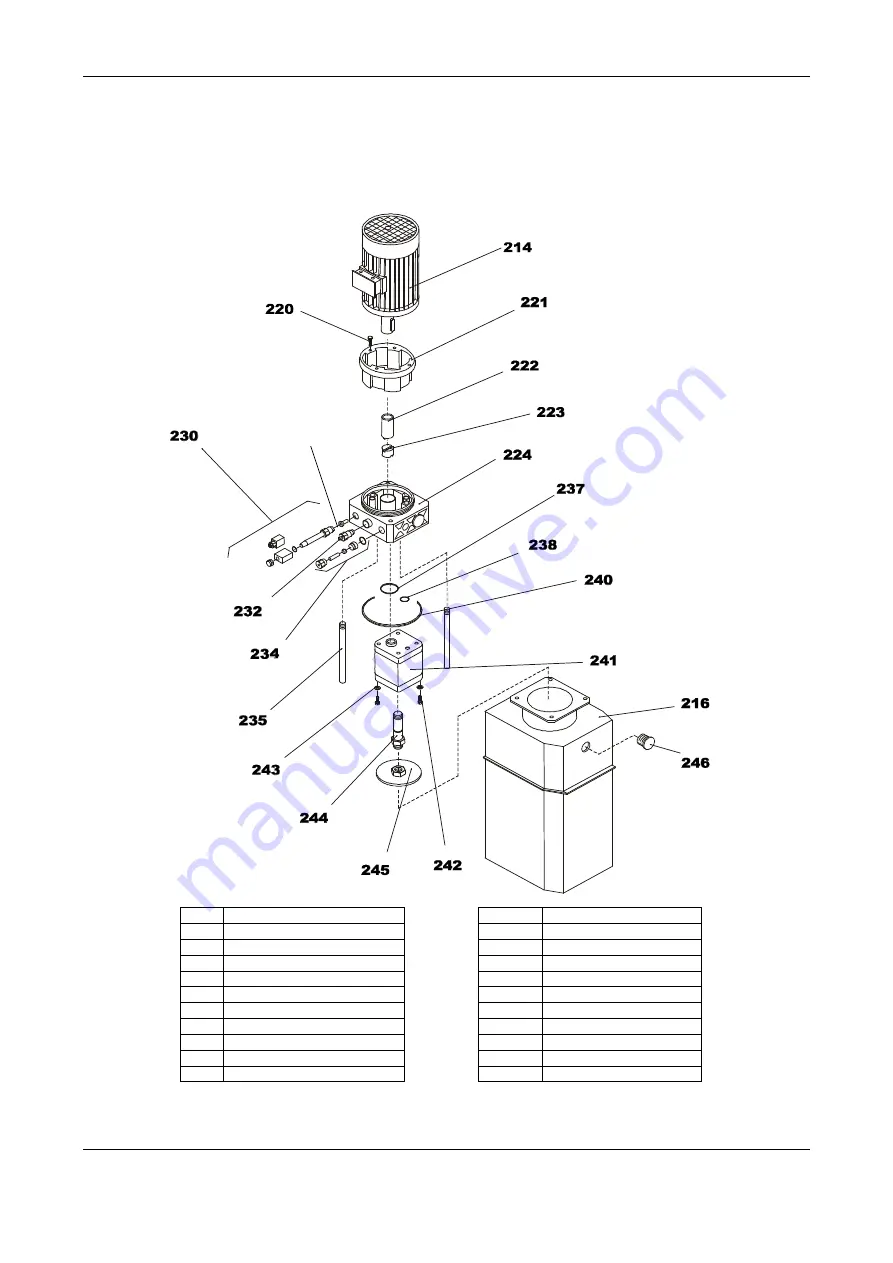
TAB.6 

– HYDRAULIC CONTROL UNIT  


247


214 

THREE PHASE MOTOR


214 

SINGLE PHASE MOTOR


216 

TANK


220 

SCREW


221 

FLANGE


222 

JOINT


223 

JOINT


224 

COLLECTOR


230 

OIL SOLENOID VALVE


232 

RELIEF VALVE


234 

CHECK VALVE


235 

DISCHARGE TUBE


237 

O RING


238 

O RING


240 

O RING


241 

PUMP


242 

SCREW


243 

WASHER


244 

SUCTION TUBE


245 

FILTER


246 

LOADING PLUG 


247 

CHOKE


Summary of Contents for FZ63/3S

Page 1: ...USE AND MAINTENANCE MANUAL SPARE PARTS CE STANDARD CONFORMITY TRANSLATION OF ORIGINAL TWO COLUMN ELECTRO HYDRAULIC LIFT FZ63 3S Edition 06 2013...

Page 2: ......

Page 3: ...y use and maintenance Carefully store this manual for any further consultation ATTENTION It is strictly forbidden to overload the lift beyond the permitted limits Installation assembly and operation m...

Page 4: ...STRUCTIONS FZ63 3S 12 ELECTRICAL CONNECTION 16 COMMAND PANEL 17 INSTRUCTIONS FOR USE 18 PROBLEMS CAUSES SOLUTIONS 19 NOISE 20 SAFETY PROCEDURES 20 MAINTENANCE 21 GREASING EVERY 3 MONTHS 22 DEMOLITION...

Page 5: ...ncepts general design principles Terminology basic methodology UNI EN ISO 12100 Part II Machinery safety Fundamental concepts general design principles Specifications and technical principles UNI EN 1...

Page 6: ...se of the lift is not permitted to wash vehicles It is forbidden to polish or sand near the lift It is forbidden to use the lift for various purposes other than those outlined by the manual To work on...

Page 7: ...by the standard It is forbidden to access the powered parts and these parts are indicated It is compulsory to only allow specialist and authorised staff carry out repairs on the parts of the system R...

Page 8: ...echanical safety devices are implemented The motor is protected from overloading in the event of overheating it stops TECHNICAL CHARACTERISTICS AND MEASUREMENTS THREE PHASE SINGLE PHASE Capacity 3500...

Page 9: ...hops declines any liability if the operator does not comply with the manufacturer s instructions TRANSPORT These lifts are dispatched in nylon packaging held in place by adhesive tape and straps on wo...

Page 10: ...The lift transmits a maximum load of 2100 Kg for each column on the floor 3 The lift must only be installed in a closed location protected from weather and sufficiently high to move the vehicle on th...

Page 11: ...t and the surrounding area to prevent the presence of unauthorised people and objects in this area that could cause sources of danger OPERATION Before operating the machine particularly for first star...

Page 12: ...rious parts from the packaging check they are intact and there are no anomalies then follow the instructions to assemble the parts following the various illustrations as a reference The installation t...

Page 13: ...cause the hole is too big or the concrete is not sufficiently consistent If you are unsure about the floor or the positioning on the supporting surface consult the authorised dealer s technical suppor...

Page 14: ...he cable 11 to check trolley height difference The cable is in the column 5 and must follow the path as displayed in the Fig passing inside the risers 15 and the beam 16 using the pulleys 12 to change...

Page 15: ...uring these operations check all the connection joints and cylinders are not leaking 17 Re assemble the casings 3 and couple the electrical control unit 20 to the casing using the prepared holes Fig 3...

Page 16: ...of the machine with an adequately sized differential circuit breaker automatic system and must be coordinated with the earthing system as specified in standard CEI 64 8 Connection to the mains must b...

Page 17: ...The power supply must be protected with a trip switch direct connection to line mains is FORBIDDEN COMMAND PANEL Fig 6 Control unit The control unit is composed of Mains light H1 Up button P1 Down but...

Page 18: ...u reach the desired height PARKING Press the down button P2 Fig 6 The position of the platform is automatically stabilised on the hooks DOWN Briefly press the up button P1 Fig 6 lifting the platform 3...

Page 19: ...Control micro Check the micro is placed at the centre of the cam as described in Fig 4 Cable assembly Descent is extremely slow The choke is not working properly Clean the choke Tubes blocked Clean t...

Page 20: ...ring handling PREVENTIVE MEASURES Avoid the formation or diffusion of oil mist in the atmosphere Avoid repeated or prolonged contact with your skin Carefully wash with soap and water Do not use irrita...

Page 21: ...ng controls every 3 months 1 Check the electrical system is safe cable insulation functionality of the device differential protection and protection conductor continuity 2 Check the locks on the vario...

Page 22: ...valve Clean the oil solenoid valve taking care not to damage the valve during dismantling and re assembly ATTENTION For the operations in point 1 the entire control unit must be removed and placed on...

Page 23: ...d in the hydraulic control unit the oil should be placed in sealed containers and sent to a specialist centre for disposal following the specific provisions on the matter planned in the user country r...

Page 24: ...SE 3 FEET PROTECTION 4 COLUMN 5 TOP PLATE 9 RACEWAY 11 BOLT 12 PULLEY 13 SPACER 14 NUT 16 CYLINDER 18 CYLINDER FITTING 20 WASHER 21 BOLT 22 CABLE 23 BRAKET 24 NUT 25 SPRING 26 TIE ROD 27 CAM 28 MICRO...

Page 25: ...21 BOLT 50 COVER 51 CASING 52 NUT 53 WASHER 54 NUT 55 WASHER 56 BOLT 57 PLATE 58 SPACER 60 BOLT 61 BOLT 62 TOP PLATE 63 BOLT 64 WASHER 65 BRAKET 66 NUT 67 BOLT 68 WASHER 70 NUT 71 WASHER 72 SPACER 73...

Page 26: ...LAST 93 BOLT 94 WASHER 95 ROLL 96 SPACER 97 PIVOT 98 PLATE 99 CHAIN FITTING 100 SPACER 102 NUT 103 WASHER 104 WHEEL 105 SPRING 106 BOLT 107 WASHER 108 NUT 109 WASHER 110 BRAKET 111 BOLT 112 BOLT 115 N...

Page 27: ...ARM 14 NUT 15 SEEGER 16 SEEGER 17 SEEGER 18 SCREW 19 SCREW 20 DISC 21 ARM 22 SCREW 23 NUT 24 SCREW 25 SCREW 26 PROTECTION No DESCRIPTION 1 ARM 2 ARM 3 PAD 4 BUSHING 5 LOCK 6 PIN 7 SUPPORT 8 WASHER 9...

Page 28: ...PACER 178 SLEEVE 179 ROD 180 HEAD 184 BOX 185 WHEEL 186 BEARING 187 NUT 188 SPACER 189 BOLT 191 JOINT 192 JOINT 195 TUBE 196 TUBE 198 GASKETS KIT 199 TUBE 200 JOINT 203 GASKETS KIT 207 PISTON 208 SPAC...

Page 29: ...HASE MOTOR 214 SINGLE PHASE MOTOR 216 TANK 220 SCREW 221 FLANGE 222 JOINT 223 JOINT 224 COLLECTOR 230 OIL SOLENOID VALVE 232 RELIEF VALVE 234 CHECK VALVE 235 DISCHARGE TUBE 237 O RING 238 O RING 240 O...

Page 30: ...Maintenance Manual Spare Parts TAB 7 PNEUMATIC SYSTEM 250 PNEUMATIC CYLINDERS 251 HARD TUBE 252 COIL 254 JOINT 255 JOINT 258 HARD TUBE 259 AIR SOLENOID VALVE 261 REEL 262 JOINT 300 BLOCK 301 JOINT 302...

Page 31: ...stem function it is compulsory to install a lubricator filter DESCRIPTION REF A TANK 216 B HYDRAULIC CYLINDERS Tab 5 C PUMP 241 D SUCTION FILTER 245 E RELIEF VALVE 232 F CHECK VALVE 234 H OIL SOLENOID...

Page 32: ...Page 32 Use and Maintenance Manual Spare Parts THREE PHASE ELECTRIC DIAGRAM...

Page 33: ...Use and Maintenance Manual Spare Parts Page 33...

Page 34: ...and Maintenance Manual Spare Parts IG MAIN SWITCH KM1 CONTACTOR QF1 CIRCUIT BREAKER FU1 FUSES TC1 TRANSFORMER FU2 FUSE HL1 SIGNAL LIGHT PE EMERGENCY BUTTON S1 CONTROL P1 UP BUTTON P2 DOWN BUTTON P3 H...

Page 35: ...Use and Maintenance Manual Spare Parts Page 35 SINGLE PHASE ELECTRIC DIAGRAM...

Page 36: ...Page 36 Use and Maintenance Manual Spare Parts...

Page 37: ...nance Manual Spare Parts Page 37 IG MAIN SWITCH KM1 CONTACTOR QF1 CIRCUIT BREAKER FU1 FUSES TC1 TRANSFORMER FU2 FUSE HL1 SIGNAL LIGHT PE EMERGENCY BUTTON S1 CONTROL P1 UP BUTTON P2 DOWN BUTTON P3 HOOK...

Page 38: ...rom any liability deriving from use of the lift In the event of damage illegibility or removal of one or more stickers on the machine ask for the positioning no necessary to replace it re position the...

Reviews: