background image

47 


Warranty 


LIMITED WARRANTY 

 
Four-Year Limited Warranty: Falcon Electric warrants that this product will be free from defects in 
materials and workmanship for a period of four years from the date of shipment within the 50 states and 
Canada (Domestic). The warranty is limited to one year for all other destinations (International). 

Procedures: Any defective product must be returned to Falcon. No product can be returned without first 
obtaining a Return Material Authorization (RMA) number from Falcon.  Falcon will repair, replace or 
refund the purchaser price, at Falcon’s sole discretion, for any defective product that is returned to 
Falcon with an RMA number. For defective product sold domestically, as defined above, returned within 
30 days of shipment, Falcon will pay for the shipping costs to and from its service center. For a 
defective product returned after 30 days but within 90 days of shipment, Falcon will only pay for 
shipping costs in sending the new or repaired product back to the end-user. For a defective product 
returned more than 90 days after shipment, all shipping costs will be borne by the end-user. Falcon will 
not pay any shipping costs sold internationally, as described above. 

Exclusions: This limited warranty does not cover damage caused by: (i) improper installation, misuse or 
neglect; (ii) unauthorized repairs or modi

fi

cations or use of unauthorized parts; (iii) acts or events 

outside of Falcon’s control, such as 

fi

re, accidents, impacts; (iv) normal wear and tear, such as cleaning 

and replacement of batteries.  

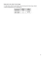
The warranty is null and void if: (i) the product is used in conjunction with life support equipment; (ii) 
The factory seal is broken or shows signs of tampering; or (iii) the battery is allowed to discharge below 
the minimum battery cutoff point. To prevent this discharge, remove the battery fuse, or switch the 
battery disconnect to the “off” position when the unit is to be stored without the AC power being 
supplied to the UPS for more than two days. The battery must be recharged every four to six months 
when not in use. This limited warranty is not transferable.  

Limitations: In no event is Falcon responsible for any special, indirect, secondary or consequential 
damages, such as personal injury, damage to property, loss of data, lost pro

fi

ts, etc. In no event will 

Falcon’s liability under this limited warranty exceed the purchase price paid for the product in question.  

Disclaimers: The limited warranties set forth in this document are the only warranties that apply to 
Falcon’s products. All other warranties are expressly disclaimed, including any implied warranties of 
merchantability or 

fi

tness for a particular purpose. This warranty gives you speci

fi

c legal rights, and you 

may have other legal rights that vary from state to state. 


Summary of Contents for SSG6KRM-2

Page 1: ...Falcon Electric Inc All other brand names and trademarks are the property of their respective owners The information and specifications stated in this document are subject to change without notice OM4...

Page 2: ...2...

Page 3: ...ls 17 Getting Started 19 Installation Environment 19 Rackmount Installation 20 Battery Bank Installation 23 Electrical Wiring 24 Output Configurations 26 UPS Start up Procedure 28 UPS Operation 30 Ope...

Page 4: ...th robust components and materials the SSG assures reliable operation and a long service life in stressful environments It is a true on line industrial UPS 12 year rated batteries cut service costs Th...

Page 5: ...5 Double Conversion On line UPS Block Diagram...

Page 6: ...reduce the risk of fire or electrical shock replace only with the same type and rating of fuse CAUTION To reduce the risk of fire connect only to a circuit provided with 30 amperes maximum branch circ...

Page 7: ...7 Symbols Important Instruction Special Note Recycle Do not dispose with ordinary trash...

Page 8: ...al scientific or data processing class equipment The SSG Industrial UPS requires minimal maintenance or monitoring if the documented installation environmental and operational specifications have been...

Page 9: ...C converter In both modes of operation the UPS inverter is online and continuously generating clean regulated AC power to the load The Isolated Gate Bipolar Transistor IGBT Pulse Width Modulation PWM...

Page 10: ...nsformer box This switch serves to provide power to the connected equipment in case of UPS failure or maintenance is required Inspecting the Equipment Visually inspect the UPS for shipping damage If t...

Page 11: ...11 Box Contents The UPS is shipped complete with all cables and accessories required for operation A full listing of the box contents is provided below SSG6KRM 2 Inverter XM6KRM 2 2 Transformer...

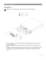
Page 12: ...12 SSGR SSGR 1 2 Models...

Page 13: ...nverter SSG6KRM 2 Front View A Function Test Button B Set Alarm Silence Button C Power Bypass Button D LCD Display UPS Transformer XM6KRM 2 2 Front MBS View M Removeable front panel N Maintenance Bypa...

Page 14: ...put Terminal Block H Communication Option Slot I Battery Connectors J Battery Fuses K DB 9 RS232 L Remote Emergency Power Off R E P O Terminal XM6KRM 2 2 Rear View O Cooling Fans P Utility Input Q UPS...

Page 15: ...ional Battery Connection 3 Battery Connection SSGR 1 SSGR 2 Rear View 4 Battery Circuit Breaker 5 Additional Battery Connection 6 Battery Connection 7 AC Power Switch 8 AC Power Cord Inlet with Fuse 3...

Page 16: ...dule Input Circuit Breaker One or more protection devices provided to protect the UPS input from an over current condition Cooling Fan One or more devices provided to maintain the proper temperature o...

Page 17: ...ell icon indicates the battery capacity The greater the battery capacity available the more internal bars will be illuminated Each bar represents 25 capacity Fan in high speed mode HS fan icon indicat...

Page 18: ...ction setting Set Alarm Silence Button Multifunctional key disables audible alarm used to scroll through metered parameters and sets the desired programmed setting Power Bypass Button Multifunctional...

Page 19: ...rack space Do not block air flow Allow a minimum of 3 inches 76 2mm clearance from the front and rear panel air vents Environment o Intended for use in a protected environment free from moisture flam...

Page 20: ...the units to the rack rails They do not support the weight of the UPS transformer or battery bank Rack slides or shelves are required Reference the following procedure to install the UPS in a standard...

Page 21: ...ion and disconnect the inner from the outer member Rack Section 4 For slide rail installation fasten the inner portion of the slide rail to the UPS on both sides with the screws provided 4 8 32 x 3 16...

Page 22: ...S with inner parts attached into the slide assemblies You may need to depress the locking mechanisms on the inner and outer parts of the slide assemblies to allow the slides to retract The UPS should...

Page 23: ...ks are shipped with the internal battery packs preinstalled 1 Remove the Battery Connector cover plates to expose the battery connectors as shown below 2 Assure the battery circuit breakers are in the...

Page 24: ...commendations Please adhere to local and national electrical codes Model Maximum Current Conductor Selection 6kVA 30 Amps Input Use 10 AWG 75 C copper wire TRQ 4 4 IN LB 30 Amps Output Use 10 AWG 75 C...

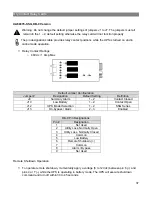
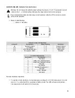
Page 25: ...25 SSG6KRM 2TXI With Transformer Module Warning Utility sources must be of the same phase...

Page 26: ...26 Output Configurations 240V 120V Split Phase L1 to L2 240VAC L1 or L2 to N 120VAC Each 120VAC winding is limited to 50 maximum of total UPS output capacity Single Output Configuration 208 240VAC...

Page 27: ...27 Single Output Configuration 120VAC...

Page 28: ...n the ON up position 2 Turn on the input circuit breaker located on the rear panel of the UPS inverter module 3 Allow 30 to 45 seconds for the UPS to complete power on self test 4 Confirm the UPS disp...

Page 29: ...then power on the load Turn off UPS Utility Power Available Warning Do not press any other buttons after the shutdown command has been initiated to prevent interruption fault alarm or unexpected outpu...

Page 30: ...capacity As capacity decreases fewer bars will remain illuminated The charger icon is turned off and the UPS will emit a continuous audible beep sequence during battery mode operation Bypass Mode Byp...

Page 31: ...battery backup is not required when equipment is drawing low current REPO Mode Remote Emergency Power Off A two pin normally closed connector is located on the rear panel of the UPS The connector is s...

Page 32: ...ery Voltage Load Percentage Input Current Percentage Internal Temperature Celsius Output Current Use the set alarm silence button to scroll through the available meter readings Actual readings will va...

Page 33: ...te battery capacity 1 While the UPS is operating in online mode press the set alarm silence button three times until the battery voltage metering is displayed 2 While the UPS is operating in online mo...

Page 34: ...On 230V Off 220V On 208V Off 1 While the UPS is online simultaneously press the function test and set alarm silence buttons until an audible beep emits to enter the configuration mode 2 Use the funct...

Page 35: ...35 Default Programmed Settings 230V Models Function Bit 6 5 4 3 2 1 0 N A N A N A N A N A N A N A N A Green Mode Disabled 230V Output...

Page 36: ...e required is a 4 Pin USB Type A M connector 4 PIN USB Type B M connector The USB and RS 232 ports cannot be used concurrently Please follow the installation and setup instructions supplied on the sof...

Page 37: ...n Jumper Designation Default Setting Definition J9 Summary Alarm 1 2 Contact Closed J10 Low Battery 1 2 Contact Open J12 UPS Model Selection 1 2 SSG Series J13 On bypass Alarm 2 3 Enabled DB 9 Pin Des...

Page 38: ...r Designation Default Setting Definition J9 Summary Alarm 1 2 Contact Closed J10 Low Battery 1 2 Contact Open J12 UPS Model Selection 1 2 SSG Series J13 On bypass Alarm 2 3 Enabled Terminal Designatio...

Page 39: ...t may be toxic CAUTION A battery can present a risk of electrical shock and high short circuit current The following precautions should be observed when working on batteries Remove watches rings or ot...

Page 40: ...following precautions should be observed to maximize battery life Connect UPS to a properly rated outlet for at least 24 hours to ensure batteries are in a fully charged state prior to long term stora...

Page 41: ...e The table below provides the typical battery service life during float trickle charge Ambient temperature greatly affects the overall battery life Temperature Period Years Float Charge 25 C 77 F 12...

Page 42: ...left side first and battery support plate as shown Then remove the right side 2 Remove the battery packs Grasp each battery pack from the sides Do not place hands on rear 3 Install the replacement bat...

Page 43: ...he utility power frequency Five short beeps continuously ___ UPS internal over temperature Cooling fan failure Check air vents for blockage Check fan operation Check ambient room temperature Six short...

Page 44: ...attery disconnects are in place turned on UPS will not provide power to the load Output only present on one receptacle No output from any output receptacle Output fails as soon as load is connected Ch...

Page 45: ...lity power surge Disconnect load from UPS output Restart UPS If error persists contact Falcon Electric Service Department 1 SOFT START FAULT CPU detects error due to excessive overload at start up aff...

Page 46: ...n a Return Material Authorization number RMA along with return shipping instructions The RMA number issued must appear on the outside of the shipping carton The original shipping container must be use...

Page 47: ...llation misuse or neglect ii unauthorized repairs or modifications or use of unauthorized parts iii acts or events outside of Falcon s control such as fire accidents impacts iv normal wear and tear su...

Reviews: