34
Programming Mode
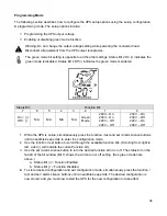
The following section describes how to con
fi
gure the UPS setup options using the setup, con
fi
guration
& programming mode. The setup options include:
Programming the UPS output voltage.
Enabling or disabling green mode function.
Warning: Do not change the output voltage setting while powering the connected load.
Disconnect all equipment from the UPS output receptacles.
The green mode bit setting is opposite to all the other settings. Status Bit 2 On (•) indicates the
green mode is disabled. Status Bit 2 Off (•) indicates the green mode is enabled.
Status Bit
Function Bit
7 6 5 4 3 2
1
0
On = (•)
Off = ( )
N/A N/A N/A N/A
Green
Mode
240V – On
230V – On
220V – Off
208V – Off
240V – On
230V – Off
220V – On
208V – Off
1. While the UPS is online, simultaneously press the function / test and set / alarm silence buttons
until an audible beep emits to enter the configuration mode.
2. Use the function / test button to scroll through the available function bits. (Scrolling from right to
left, a dot (•) will indicate the current function bit.)
3. Use the set / alarm silence button to turn the desired function bit on or off. The status bit on the
far left of the bit window (Bit 7) shows the current on or off setting. (See green mode note
above.)
a. Status Bit (•) = Function Enabled
b. Status Bit ( ) = Function Disabled
4.
To store desired configuration and exit configuration mode, simultaneously press the function /
test and set / alarm silence buttons until an audible beep emits. The desired configuration is
now stored, and you must now restart the UPS for the new configuration to take effect.
Summary of Contents for SSG6KRM-2
Page 2: ...2...
Page 5: ...5 Double Conversion On line UPS Block Diagram...
Page 7: ...7 Symbols Important Instruction Special Note Recycle Do not dispose with ordinary trash...
Page 12: ...12 SSGR SSGR 1 2 Models...
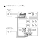
Page 25: ...25 SSG6KRM 2TXI With Transformer Module Warning Utility sources must be of the same phase...

