38
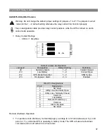
UA88376-SSG-HW, Hardwire Terminal Version
Warning: Do not change the default jumper settings of jumpers J1 to J7. The jumpers must all
remain in the 1 – 2, default setting otherwise the relay card will not function properly.
The pin designations table provides relay contact positions while the UPS is turned on and in
online mode operation.
Relay Contact Ratings
o
48Vdc / 1 Amp Max
Default Jumper Configuration
Jumper #
Designation
Default Setting
Definition
J9 Summary
Alarm
1
– 2
Contact Closed
J10 Low
Battery 1
– 2
Contact Open
J12 UPS
Model
Selection 1
– 2
SSG Series
J13
On-bypass / Alarm
2 – 3
Enabled
Terminal Designations
Terminal #
Designation
1 Not
Used
2
Utility Loss, Normally Open
3
Utility Loss, Normally Closed
4 Common
5 Low
Battery
6
Remote Shutdown (+)
7 Common
8
Alarm / Bypass
9 Not
Used
Remote Shutdown Operation
To operate remote shutdown, momentarily apply a voltage (5 to 12Vdc) between pin 6 (+) and
pins 4 or 7 (–) while the UPS is operating in battery mode. The UPS will execute shutdown
command and turn off within 30 to 45 seconds.
Summary of Contents for SSG6KRM-2
Page 2: ...2...
Page 5: ...5 Double Conversion On line UPS Block Diagram...
Page 7: ...7 Symbols Important Instruction Special Note Recycle Do not dispose with ordinary trash...
Page 12: ...12 SSGR SSGR 1 2 Models...
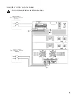
Page 25: ...25 SSG6KRM 2TXI With Transformer Module Warning Utility sources must be of the same phase...

