background image

____________________________________________________________________________

- 47 -

4.4 Communication Protocol

FTP9000 series power supplies support SCPI, Modbus and CANopen communication protocols. For LAN, USB
serial port, RS485 interface, users can choose SCPI or Modbus; for GPIB interface, only SCPI protocol is supported,
and CAN interface only supports CANopen protocol.

4.4.1 SCPI protocol

For specific content of SCPI protocol, please refer to "FTP9000 Programming Manual SCPI Edition".

4.4.2 Modbus protocol

For specific content of Modbus protocol, please refer to "FTP9000 Programming Manual Modbus Edition"

----------------------------------------------------------------------------------------------------------------------

Regarding to ModBus protocol

,

FTP9000 series support RTU communication mode only.

----------------------------------------------------------------------------------------------------------------------

4.4.3 CANopen protocol

For specific content of CANopen protocol, please refer to "FTP9000 Programming Manual CANopen Edition"

----------------------------------------------------------------------------------------------------------------------

CANopen protocol is an optional protocol.

----------------------------------------------------------------------------------------------------------------------

Summary of Contents for FTP9000 Series

Page 1: ...Programmable DC Power Supply User s Manual FTP9000 Series Copyright Faithtech Version V1 03 2021 06...

Page 2: ......

Page 3: ...date of purchase warranty within the one year warranty period Faithtech will provide free repair for all faults in the normal usage and maintenance of the product The user need prepay one way freight...

Page 4: ...n Make sure the output wire meets the specified standards and a protective cover must be installed to prevent electric shock Do not open the instrument case Operators are not allowed to open the shell...

Page 5: ...tly observed could result in injury to or death of personnel or long term heath hazards The CAUTION sign highlights an essential operating or maintenance procedure practice condition statement etc whi...

Page 6: ...18 2 6 3 Power ON Self Check 18 2 7 Connection 19 2 7 1 Input Connection 19 2 7 2 Input Connection for Multiple Power Supplies 19 2 7 3 Output Connection 20 2 7 4 Remote Sensing Connection 20 2 7 5 PR...

Page 7: ...mp down RAMP 38 3 15 Master slave Parallel 40 3 15 1 Master slave parallel connection 40 3 15 2 Master slave parallel setting 41 3 15 3 Master slave parallel function operations 42 4 COMMUNICATION INT...

Page 8: ...fit from the standard USB virtual SERIAL and LAN interfaces supporting both SCPI commands and ModBus RTU protocol Free application software programming manual and a complete set of development DLLs ar...

Page 9: ...____________________________________________________________________________ 7 1 3 Dimension diagram 1 3 1 Model of 5kW 10kW 15kW...

Page 10: ...FTP9000 Series Programmable DC Power Supply Operation Manual ____________________________________________________________________________ 8 1 3 2 Model of 20kW 25kW 30kW...

Page 11: ...l GPIB CAN RS485 Protocol SCPI MODBUS CAN Open protocols Input characteristics Input voltage 340VAC 460VAC 47Hz 63Hz Power factor 0 99 Typical Efficiency 93 Typical Operation environment Working temp...

Page 12: ...300A Power 0 60kW Model FTP9900 80 3060 FTP9900 200 1260 FTP9900 400 720 FTP9900 500 540 FTP9900 800 450 Voltage 0 80V 0 200V 0 400V 0 500V 0 800V Current 0 3060 A 0 1260A 0 720A 0 540A 0 450A Power...

Page 13: ...200 40 FTP9150 1500 30 FTP9150 2250 25 Voltage 0 1000V 0 1200V 0 1500V 0 2250V Current 0 40A 0 40A 0 30A 0 25A Power 0 15kW Model FTP9200 1000 60 FTP9200 1500 50 Voltage 0 1000V 0 1500V Current 0 60A...

Page 14: ...F S Current accuracy 0 5 F S Line regulation Voltage 0 02 F S Current 0 05 F S Power 0 05 F S Load regulation Voltage 0 05 F S Current 0 15 F S Power 0 75 F S Voltage measurement Resolution 16bits Ac...

Page 15: ...utput protection 2PIN 5 08mm terminal 1 PCS Voltage remote sense connection terminal 2PIN 2 54mm terminal 1 PCS Master Slave parallel connection terminal USB communication cable 1 PCS For connecting P...

Page 16: ...l Power switch TFT color screen Keyboard Rotary knob 2 3 Keyboard Figure 2 2 FTP9000 keyboard Table 2 2 Key Function Descriptions Button Key Name Description Voltage Setting Key Switch to output setti...

Page 17: ...lear Key Clear the occurred protection and warning messages Main Menu Key Enter the main menu Compound Function Key Work with other key together Lock or unlock the keyboard In locked state only and ar...

Page 18: ...ters display area Displays readback voltage current power measurement result etc However the actual displayed information varies for example in V I P static output mode the area displays output voltag...

Page 19: ...negative output terminal Do not reverse the connections 3 Output The output terminals of the DC Power Supply 4 GPIB or CAN RS485 The remote controller uses the GPIB connector to connect to a PC for r...

Page 20: ...pply need to be connected to L1 L2 L3 and grounding terminal Please refer to Table 6 1 Recommended Wire Diameters for Cables for the selection of input wire diameters to avoid potential safety hazards...

Page 21: ...to the earth Under no circumstances shall this DC Power Supply be operated without an adequate ground connection 2 Installation of the power cord must be done by a professional and compliant with loc...

Page 22: ...dequate so as to carry the maximum applied current 2 7 4 Remote Sensing Connection FTP9000 series power supplies are able to compensate for the voltage drop caused by output connecting cables Use two...

Page 23: ...ol 4 DGND Digital ground 5 DGND Digital ground 6 AGND Analog ground 7 VMON Output Output Voltage monitoring port monitoring output range 0 5VDC corresponds to 0 100 F S rated voltage of the power supp...

Page 24: ...e by default In this mode the user operates the power supply through the front panel keyboard The LCD screen provides users with display functions such as parameter viewing measurement display and sta...

Page 25: ...Set communication error time out range 0 0 60 0s set 0 to turn off this protection Detect RV Turn on off reverse voltage protection default value Closed Limit V_MAX Upper limit of static output volta...

Page 26: ...0 254 default 160 GPIB set GPIB address range 0 30 default 5 Protocol SCPI MODBUS default MODBUS Factory Reset to factory setting Reboot the machine to take effect Others Language Simplified Chinese...

Page 27: ...Press power supply enters static output mode the cursor for voltage set blinks also you can rotate the knob to highlight the voltage setting and press to edit voltage 2 Use to set the value and press...

Page 28: ...e in which the output power can be changed by setting the output power value in this situation CP is displayed in status prompt area 3 3 2 Limit Voltage Current Power Set FTP9000 series power supply a...

Page 29: ...as below Set System Edit About Samp Rate 10Hz Prio SLT Volt Vslew UP 5000 0 V s Vslew DN 5000 0 V s Islew UP 2000 0 V s Islew DN 2000 0 V s Figure 3 3 Voltage Current Slew Rate Set 3 Select parameter...

Page 30: ...priority while Curr stands for current priority 3 6 Output Control The power supply s output is turned off when it is switched on Users control its output via front panel key key is lighted suggests...

Page 31: ...XT S Trigger Figure 3 8 External Programming Set 3 Select APG_V APG_I APG_P for performing voltage programming current programming or power programming turn on off operations respectively the status p...

Page 32: ...ree behaviors Trigger Default setting Used as trigger signal The port detects a valid low level pulse that is a trigger signal is received Toggle Used as power supply output ON OFF control signal The...

Page 33: ...11 Output Voltage Current And Monitoring Output 3 7 4 Output Mode Status Monitoring The FTP9000 series power supply has an output mode signal port and a fault indication signal port The port outputs a...

Page 34: ...ervoltage protection hardware overvoltage OV and software overvoltage OVP Hardware overvoltage protection OV It is triggered once the output voltage exceeds 105 rated output voltage and OV is prompt o...

Page 35: ...g time can be set as in Figure 3 12 Protection Set range 0 0 60 0 seconds Overtemperature protection It is triggered once the temperature of inner power components exceeds allowed temperature range OT...

Page 36: ...position 2 voltage 24V current 20A power 2000W maximum voltage and current slew rate Shortcut Function 1 Press 2 Select Set System and press then select Others and press again 3 Set Shortcut as ON so...

Page 37: ...to run cyclically for a specified times set to 0 means infinite loop Link can add other sequence file into test set to 0 means no linked sequence file When the sequence test is turned on the highest...

Page 38: ...lly 6 Set Link press to validate it the editing cursor will move to SEQ Step automatically 7 Set SEQ Step press to validate it the editing cursor will move to V_Set automatically 8 Set V_Set press to...

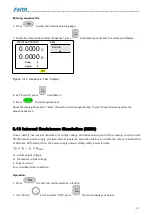
Page 39: ...e current sequence step Cycle shows how many cycles the sequence have run 3 13 Internal Resistance Simulation RESI Since a battery has internal resistance its output voltage will decrease along with t...

Page 40: ...RESI 2 2 0 0000 V 0 0000 A 0 000 Resistance 0 000 Off Figure 3 16 Output Test For Battery Simulating 3 Set the corresponding test parameters 4 Press to turn on battery simulating output Table 3 5 RESI...

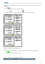
Page 41: ...0W RAMP 1 3 0 0000 V 0 0000 A 0 000 w Voltage A 0 000 V Voltage B 0 000 V Voltage C 0 000 V Off 80V 510A 15000W RAMP 2 3 0 0000 V 0 0000 A 0 000 w Vslew rate AB 0 000 V s Vslew rate BC 0 000 V s I_Set...

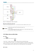
Page 42: ...rent P_Set Set output power range 0 Max output power V Voltage A Voltage C Voltage B t Figure 3 18 RAMP Function Parameter Set 3 15 Master slave Parallel 3 15 1 Master slave parallel connection FTP900...

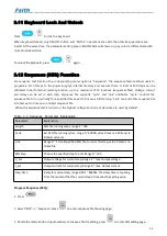
Page 43: ...unit if you want to compensate voltage line loss 4 Does not support master slave series operation 3 15 2 Master slave parallel setting Slave setting 1 Press to enter main menu interface 2 Select Set P...

Page 44: ...rameter setting The master power supply specifications will be updated 3 15 3 Master slave parallel function operations Simply operate the master unit to control the whole group if you have configured...

Page 45: ...the fault slave unit code requires user to press to clear the fault protection 1 Set slave unit first so as to avoid master unit communication error 2 Multiple power supplies have been set as master u...

Page 46: ...rst please set IP as 192 168 1 123 subnet mask as 255 255 255 0 then set the IP address of the connecting PC to be in the same segment with the power supply IP Different IP segments will result in com...

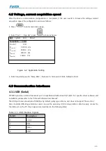
Page 47: ...2 Application Setting 3 Select required speed in Samp Rate there are 5 choices select able Default is 10Hz 4 3 Communication Interfaces 4 3 1 USB Serial FTP9000 provides a USB virtual serial port com...

Page 48: ...address of the PC and the power supply are in the same network segment and that there is no duplicate IP address with the power supply in this network segment otherwise it will not be able to connect...

Page 49: ...AN interface only supports CANopen protocol 4 4 1 SCPI protocol For specific content of SCPI protocol please refer to FTP9000 Programming Manual SCPI Edition 4 4 2 Modbus protocol For specific content...

Page 50: ...ate Overtemperature Protection OTP1 OTP2 1 The ambient temperature is too high 2 Bad ventilation 3 Fan damaged 1 Operate the instrument within an ambient temperature of 0 40 C 2 Ensure the instrument...

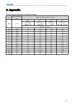
Page 51: ...ions AWG mm2 60 75 85 90 Wire type RUW T UF Wire type RHW RH Wire type V MI Wire type TA TBS SA AV Rated Current A 14 2 08 20 20 20 20 12 3 31 25 25 30 30 10 5 26 30 35 40 40 8 8 36 40 50 55 55 6 13 3...

Reviews: