Drive modules
DRIVE MODULES
Mo
dula
r d
riv
es
3.
141
DDS
HARDWARE
Ref.1310
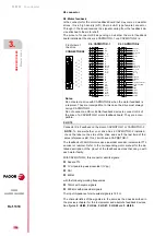
Dip-Switches (DS1, DS2)
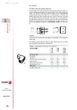
Adjustment outputs
With these outputs and a potentiometer, the user can obtain a variable an-
alog voltage for adjusting the servo system during setup.
The voltage, with no load, at these pins is ±15 V DC.
The electrical circuit necessary to obtain a reference voltage and the rec-
ommended resistance values to obtain an approximate range of ±10 V
DC for the Vref are described next:
F. H3/78
Factory settings of the dip-switches (DS1, DS2).
A1
1
1
X7
-A
N
A
LOG I
/Os
X6
-D
IG
IT
A
L
I/O
s
P2
P1
DS1
DS2
MANDATORY.
The status of the dip-switches (DS1, DS2) must not be
changed by the operator.
F. H3/79
Adjustment outputs.
Range ±10 V
Rext.
R’
1 k
0
5 k
820
10 k
1.8 k
20 k
3.3 k
5
4
1
7
+15 V DC
X7
GND
Vref
R'
R'
Rext
DRIVE
6
-15 V DC
8
10
Summary of Contents for APS-24
Page 1: ...DRIVE DDS Hardware manual Ref 1310...
Page 6: ...I 6 DDS HARDWARE Ref 1310...
Page 9: ......
Page 10: ......
Page 11: ......
Page 12: ......
Page 16: ...16 Ref 1310 DDS HARDWARE...
Page 30: ...1 DESCRIPTION 30 Description DDS HARDWARE Ref 1310...
Page 94: ...2 POWER SUPPLIES 94 Power supplies DDS HARDWARE Ref 1310...
Page 188: ...3 DRIVE MODULES 188 Drive modules DDS HARDWARE Ref 1310...
Page 204: ...4 AUXILIARY MODULES 204 Auxiliary modules DDS HARDWARE Ref 1310...
Page 232: ...SELECTING CRITERIA 5 232 Selection criteria DDS HARDWARE Ref 1310...
Page 266: ...7 CABLES 266 Cables DDS HARDWARE Ref 1310...
Page 312: ...8 INSTALLATION 312 Installation DDS HARDWARE Ref 1310...
Page 326: ...9 FUNCTIONAL SAFETY 326 Functional safety DDS HARDWARE Ref 1310...
Page 354: ...10 CONNECTION DIAGRAMS 354 Connection diagrams DDS HARDWARE Ref 1310...
Page 378: ...12 SALES REFERENCES 378 Sales references DDS HARDWARE Ref 1310...
Page 384: ...13 COMPATIBILITY 384 Compatibility DDS HARDWARE Ref 1310...
Page 385: ......


