background image

Updating the Firmware

Firmware for the TLP Pro 725 series touchpanels can be upgraded using Toolbelt or the 
touchpanel web page. Before starting, consult your IT team and ensure that the touchpanel has 
a unique IP address.

Downloading Firmware

1. 

Power on a computer that is connected to the same network as the touchpanel.

2. 

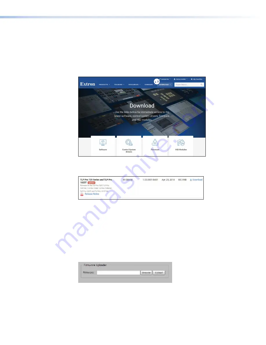
Go to 

www.extron.com

, click 

Download

 (see figure 27, 

1

) and then click 

Firmware

 (

2

).

1

1

2

2

Figure 26. 

Firmware Download Center

3. 

Click the letter 

T

 from the alphabet menu.

4. 

Scroll down the page until you find the firmware for your TLP Pro model.

1

1

2

2

Figure 27. 

TLP Pro Firmware download

5. 

Click 

Release Notes

 (see figure 19, 

1

)for more information about the firmware (optional).

6. 

Click 

Download

 (

2

).

7. 

Enter the required information and click the download button. An executable (.exe) file is 
downloaded to your computer. Run this program to place the firmware on your computer for 
future use. Make a note of the folder where the firmware is saved.

Updating Firmware Using the Touchpanel Web Page

1. 

If you have not already done so, download the firmware file to a computer on the same 
network as the touchpanel (see “Downloading Firmware” above).

2. 

Open the 

Touchpanel Web Page

 (see the previous page).

Figure 28. 

Touchpanel Web Page: Firmware Uploader

3. 

Click 

Browse

 and navigate to the firmware location.

4. 

Click 

Upload

. The firmware file is uploaded to the touchpanel. To complete the upload, 

follow the on-screen instructions.

Updating Firmware Using Toolbelt

For information about using Toolbelt to update the firmware, see the 

Toolbelt Help File

.


TLP Pro 725C Series Touchpanels • Configuration Software

29

Summary of Contents for TouchLink TLP Pro 725C NC

Page 1: ...TLP Pro 725C Series User Guide TouchLink TouchLink Pro Touchpanel Control Systems 68 3319 01 Rev B 01 19 ...

Page 2: ...nce importantes qui se trouvent dans la documentation fournie avec le matériel Pour en savoir plus sur les règles de sécurité la conformité à la réglementation la compatibilité EMI EMF l accessibilité et autres sujets connexes lisez les informations de sécurité et de conformité Extron réf 68 290 01 sur le site Extron www extron com Istruzioni di sicurezza Italiano AVVERTENZA Il simbolo se usato su...

Page 3: ... Suppression Codec Connect DDSP Digital Display Sync Processing DMI Dynamic Motion Interpolation Driver Configurator DSP Configurator DSVP Digital Sync Validation Processing eLink EQIP Everlast FastBite FOX FOXBOX IP Intercom HelpDesk MAAP MicroDigital Opti Torque PendantConnect ProDSP QS FPC QuickSwitch Front Panel Controller Room Agent Scope Trigger ShareLink SIS Simple Instruction Set Skew Free...

Page 4: ... from that to which the receiver is connected Consult the dealer or an experienced radio TV technician for help In order to maintain compliance with FCC regulations shielded cables must be used with this equipment Operation with non approved equipment or unshielded cables is likely to result in interference to radio and TV reception The user is cautioned that changes and modifications made to the ...

Page 5: ...ference Safety Notices Antenna Warnings WARNING The radiated output power of the wireless device is far below the FCC radio frequency exposure limits Nevertheless the unit should be used in such a manner that the potential for human contact during normal operation is minimized To avoid the possibility of exceeding the FCC radio frequency exposure limits you should keep a distance of at least 20 cm...

Page 6: ...ay only operate using an antenna of a type and maximum or lesser gain approved for the transmitter by Industry Canada To reduce potential radio interference to other users the antenna type and its gain should be so chosen that the equivalent isotropically radiated power e i r p is not more than that necessary for successful communication This radio transmitter has been approved by Industry Canada ...

Page 7: ...entation d Industrie Canada cet émetteur radio doit être utilisé uniquement avec une antenne d un certain type et d un gain maximal ou inférieur approuvé pour l émetteur par le ministère Afin de réduire les éventuelles interférences électromagnétiques préjudiciables aux autres utilisateurs il est essentiel de choisir le type d antenne et son gain de telle sorte que la puissance isotrope rayonnée é...

Page 8: ...computer or device responses mentioned in this guide the character 0 is used for the number zero and O represents the capital letter o Computer responses and directory paths that do not have variables are written in the font shown here Reply from 208 132 180 48 bytes 32 times 2ms TTL 32 C Program Files Extron Variables are written in slanted form as shown here ping xxx xxx xxx xxx t SOH R Data STX...

Page 9: ...tional 15 Panel Features 16 TLP Pro 725C Front Panel and Enclosure Features 16 TLP Pro 725C Base Features 17 On screen Menus 19 Setup Menu 19 Status 19 Network 20 Display 22 Audio 23 Advanced 24 Configuration Software 25 Configuration Software 25 Installing GUI Designer Global Configurator Toolbelt and Global Scripter 26 Using the Software 27 Touchpanel Web Page 28 Updating the Firmware 29 Downloa...

Page 10: ...TLP Pro 725C Series Touchpanels Contents x ...

Page 11: ...satility and adaptability to the configuration and control of an AV system The screen layout is designed with the Extron GUI Designer software The functions can be assigned to the screen objects with the Extron Global Configurator Plus and Global Configurator Professional configuration software or with Global Scripter programming software A motion sensor light sensor and a speaker provide sleep mo...

Page 12: ...stem for your collaboration environment Integrated side clamps secure enclosure to the furniture surface the Cable Cubby can be secured in place without additional parts or tools System connection status indicator the communication LED provides visual feedback if the touchpanel is not communicating with a control processor Automatic clock synchronization allows the touchpanel to display the accura...

Page 13: ... Extron IPCP Pro 250 IP Link Pro Control Processor Ethernet Figure 1 Application Diagram Requirements Software For a complete list of the requirements for running GUI Designer Global Configurator Plus and Professional Global Scripter and Toolbelt see the Extron web page www extron com for that software NOTE These touchpanels are not compatible with Global Configurator 3 or GUI Configurator Hardwar...

Page 14: ...ates and configuration of network settings system utilities and user management for TouchLink Pro devices Global Scripter Provides an integrated development environment for Extron control systems programming See Configuration Software on page 25 2 Before starting to install the TLP Pro 725C obtain the following network information from your network administrator Dynamic Host Configuration Protocol...

Page 15: ...ces 4 Set up the touchpanels for network communication Connect the PC that you are using for setup the Extron control processor and the touchpanel to the same Ethernet subnetwork Use the Setup Menu see page 19 or Toolbelt to set the DHCP status and if required the IP address subnet mask gateway and related settings for the touchpanel 5 Configure the TLP Pro touchpanels the GUI Designer Help File t...

Page 16: ...ctors on page 8 The number and type of AAPs required for the installation The location of devices that connect to the AAPs either above or below the table 2 Verify that you have the correct template or dimensions see Cut out Dimensions on page 9 3 Decide on the method for cutting a hole in the table see Cutting the Surface on page 9 There are three methods available Hand router and template see pa...

Page 17: ... Pro 725C Included Parts Open the shipping container and verify that the following parts are present TLP Pro 725C or TLP Pro 725C NC 1 4 40 Screw 8 6 32 Screw 8 6 Star Washer 8 3 8 Hole Plug 12 1 4 Hole Plug 4 8 cable Cable Pass through Plate 2 3 space AAP Frame 2 3 space Connectivity Bracket 2 Figure 3 Parts Included with the TLP Pro 725C NOTE Active or Passive AAPs must be purchased separately s...

Page 18: ...damage Vertical mounting is used if space or access makes horizontal mounting difficult To satisfy ADA compliance requirements there is also an option to mount the retractors at a 30 angle see the Retractors User Guide which is available at www extron com 1 60 41 mm 17 00 432 mm 23 6 599 mm 21 00 533 mm 1 60 41 mm 29 6 752 mm 23 00 584 mm Retractor Mounting Clearance Standard Models XL Models 15 0...

Page 19: ... hole in the furniture or other surface Pay special attention to the direction the unit will face The connector access side is underlined see CNC wood router on the next page Extron is not responsible for miscut mounting holes Utilisez le gabarit de détourage métallique approprié ou reportez vous aux dimensions de découpe de la surface indiquées ci après avant de découper le meuble ou la surface F...

Page 20: ...m ak e su re th e pa ge is no t sc ale d 3 Re m ov e th e su rfa ce cu t o ut ar ea g ra y fro m th e te m pl at e by cu tti ng alo ng th e re d lin e DO NO T CU T th e gr ay do tte d lin es 4 Me as ur e th e cu to ut an d te m pl at e Ma ke su re th e di m en sio ns ar e th e sa m e as th os e sh ow n 5 Pl ac e th e te m pl at e an d m ar k th e po sit io n on th e m ou nt in g su rfa ce wh er e ...

Page 21: ...bottom of the AAPs 2 3 Secure the AAP frame to the connectivity module using the four provided 4 40 screws 3 4 Insert the AAP module assembly into the Cable Cubby see Installing Modules on the next page Preparing Pass through Cable Modules 3 2 1 4 Figure 8 Preparing Pass through Cable Modules 1 Pass the cables through the connectivity module from the bottom see figure 8 1 2 Insert the cable into t...

Page 22: ...e modules using four of the provided 6 32 pan head mounting screws and star washers 2 Figure 9 Installing Power Modules in the TLP Pro 725C To install the power cable pass through or AAP modules follow these instructions 1 Insert the module into the cable cubby see figure 9 1 Make sure the mounting holes on the module line up with the holes on the touchpanel If you are installing retractors they s...

Page 23: ...n à un boîtier d encastrement et gardez l alimentation éteinte jusqu à ce que l installation soit complète WARNING Risk of electric shock If the power cable is installed next to the retractors ensure the power cable cannot get tangled in the cable retractor mechanism AVERTISSEMENT Risque de décharge électrique Si le câble d alimentation est installé à côté des rétracteurs assurez vous qu il ne pui...

Page 24: ...re that the lever is down Slide the clamp all the way up against the bottom of the table Ensure the TLP Pro 725C is firmly seated in the table Rotate the lever up to secure the enclosure 2 1 3 Lever Figure 10 Mounting the TLP Pro 725C Enclosure Locking Plate NOTE To lower the side clamp turn the lever down then press and hold the locking plate while sliding down the clamp 1 Rotate the side clamps ...

Page 25: ...s 2 Secure the Retractors with the included mounting pin and clip Secure the locking screw on each Retractor Do not overtighten 5 Figure 11 Installing Cable Retractors 1 Slide the Retractor bracket into the enclosure see figure 11 1 2 Secure the bracket to the enclosure with the provided 6 32 pan head screws and star washers 2 3 Mount the enclosure into the table see Mounting the TLP Pro 725C Encl...

Page 26: ...creen display is restored and active C Communication LED Shows the configuration and connection status of the touchpanel Unlit during normal operation the touchpanel is configured and connected to an IP Link Pro control processor Blinks red if the touchpanel has been configured but is not connected to an IP Link Pro control processor Lit solidly if the touchpanel is not configured and is not conne...

Page 27: ...h this port Connect the touchpanel to a PoE power injector using a twisted pair cable terminated with an RJ 45 connector Connect the power injector to the LAN through a nework switch The network port has two LEDs The green LED lights steadily to indicate that the touchpanel is connected correctly to a network The yellow LED blinks to indicate that data is being passed to or from the touchpanel NOT...

Page 28: ...upply they are intended to be supplied by a UL Listed power source marked Class 2 or LPS and output rated 48 VDC or 56 VDC PoE minimum 0 35 A or UL Listed Extron XTP DTP remote power source Si ces produits ne sont pas fournis avec une source d alimentation ils doivent être utilisés avec une source d alimentation certifiée UL de classe 2 ou LPS avec une tension nominale 48 Vcc ou 56 Vcc PoE 0 35 A ...

Page 29: ...f any screen to open the Status screen Status Display Audio Advanced Exit Network Info Model TLP Pro 725C Part Number 60 1564 02 Firmware Version 1 02 0001 b001 Network IP Address DHCP Host Name Off 192 168 254 251 TLP AB CD EF Display Resolution GUI Project Sleep Timer 1024x600 N A 5 Minutes Audio Master Volume Master Mute Off 99 Advanced Controller IP N A Project Size N A Bootloader Version 1 03...

Page 30: ...gned by DHCP press On If the IP address is to be assigned manually press Off The selected button is highlighted in yellow When DHCP is off the Host Name is grayed out and cannot be edited All addresses can be edited as shown in figure 7 When DHCP is on the Host Name can be edited The addresses are grayed out and cannot be edited because they are set by the DHCP server If IP addresses are assigned ...

Page 31: ...nter an invalid number for example 892 you are able to enter the 89 but the 2 cannot be entered Click Back to delete the last digit If no value has been entered for the selected octet pressing Back moves the cursor back to the previous octet e Press the next octet button and enter a value f Repeat steps c e until values have been entered for all four octets g Press OK to save the changes and retur...

Page 32: ... enters sleep mode when the screen goes dark to save power Toggle between On and Off If the sleep timer is on use the arrows to adjust the value between 1 and 120 minutes Auto Brightness When auto brightness is on the touchpanel provides a suitable amount of backlighting that is automatically calculated from the amount of ambient light detected by the light sensor see figure 12 D on page 16 LCD Br...

Page 33: ... all the other sound volume settings For example if the master volume is set to 80 80 percent of maximum even when the sound volume is set to 100 it is equivalent to only 80 percent of maximum Click Sets the volume for audible feedback that accompanies events such as a screen button being pressed Sound Sets the volume of audio from any audio file playback Click on the Speaker icon at the bottom of...

Page 34: ...e panels are read only providing information about the system the Global Configurator Project and the GUI Designer Project Menu PIN The PIN setup options allow you to enable disable or change the setup menu PIN The PIN is a 4 digit number Each digit can have any value from 0 9 1 Select the first digit of the PIN When selected it is highlighted in yellow Enter New Menu PIN 4 5 6 7 8 9 0 2 1 3 2 3 4...

Page 35: ...dows based application You can either customize an existing template or create an entirely new interface GUI Designer offers several templates After the user interface has been designed on a PC the project is saved built and imported into Global Configurator where the appropriate control functions are assigned to the text and graphic items of the interface After assigning the control functions the...

Page 36: ...igner Global Configurator Toolbelt and Global Scripter can be downloaded from www extron com 1 Select the Download button see figure 23 1 and then click the Software option 2 1 1 2 2 Figure 23 Extron Download Page You may see the product immediately for example Global Configurator Plus and Professional see figure 24 2 Use the left and right arrows 3 to scroll through all the highlighted products I...

Page 37: ...am and follow the on screen instructions 3 Run the executable file to install the software By default your computer creates a new folder at C Program Files Extron or C Program Files x86 Extron Using the Software GUI Designer Use the GUI Designer software to design the screen layout for the touchpanel see the GUI Designer Help file for step by step instructions and more detailed information Global ...

Page 38: ...he touchpanel default web page enter the IP address of the touchpanel into the web browser of a PC connected to the same subnet A dialog box opens asking for your user name and password By default the user name is admin and the password is extron both user name and password are all lower case Figure 25 shows the TLP Pro 725M web page The web pages for the other touchpanels are very similar Figure ...

Page 39: ...k Download 2 7 Enter the required information and click the download button An executable exe file is downloaded to your computer Run this program to place the firmware on your computer for future use Make a note of the folder where the firmware is saved Updating Firmware Using the Touchpanel Web Page 1 If you have not already done so download the firmware file to a computer on the same network as...

Page 40: ... of a firmware update that failed or incompatibility issues arising with user loaded firmware Activation To start the Use Factory Firmware reset mode and replace firmware 1 Remove power from the touchpanel 2 On the touchpanel hold down the recessed Reset button see figure 13 B while re applying power to the unit When power is restored the Reset LED C lights Hold the Reset button for a further 2 se...

Page 41: ...conds again at 6 seconds and again at 9 seconds 2 Release and press Reset momentarily for 1 second within 1 second Nothing happens if the momentary press does not occur within 1 second Result Reset to Factory Defaults mode performs a complete reset to factory defaults except the firmware Does everything Reset All IP Settings mode does Removes touchpanel user interface layout and configurations Res...

Page 42: ...ty does not apply if the fault has been caused by misuse improper handling care electrical or mechanical abuse abnormal operating conditions or if modifications were made to the product that were not authorized by Extron NOTE If a product is defective please call Extron and ask for an Application Engineer to receive an RA Return Authorization number This will begin the repair process USA 714 491 1...

Reviews: